Economic Analysis of Alternative Transition Pathways in Fuel Cycle
This study explores economic considerations in fuel cycle transition by analyzing alternative pathways to improve efficiency and reduce costs. Strategic buildout and leveraging of low-enriched uranium for fast reactors are key strategies to enhance the economics of transition pathways. The research aims to identify lower-cost transition pathways for different fuel cycle scenarios, maximizing cost differentials through adjustments in separations and fuel fabrication facilities.

Download Presentation

Please find below an Image/Link to download the presentation.
The content on the website is provided AS IS for your information and personal use only. It may not be sold, licensed, or shared on other websites without obtaining consent from the author. Download presentation by click this link. If you encounter any issues during the download, it is possible that the publisher has removed the file from their server.
E N D
Presentation Transcript
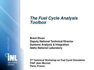
Economic Analysis of Alternative Transition Pathways to Improve Economic Considerations in Fuel Cycle Transition Brent Dixon Deputy National Technical Director Systems Analysis & Integration Idaho National Laboratory www.inl.gov Co-authors: Jason Hansen, Ross Hayes, Piyush Sabharwall 3rdTechnical Workshop on Fuel Cycle Simulation FIAP Jean Monnet Paris, France
Problem Statement Transition analysis reveals weakness in promising fuel cycle transition alternatives (Hoffman et al. 2015) Low capacity factors arise from facilities built at first demand but under utilized Low capacity factors imply higher unit costs, less efficient systems Physics analysis shows that de-coupling is possible if SFRs started on LEU with enrichment up to 19.75% (Hoffman et al. 2015; Dixon et al. 2016)
Strategic buildout improves economics Delaying the time when separations facilities brought online reduces life cycle costs while improving capacity utilization (Dixon et al. 2016) Delay requires more fissile material in system, as some sits longer in storage Tradeoff in increased fuel storage costs versus reduced separations facility unit costs
Study Goals and Objectives Research Question: Can the economics of transition pathways be improved by leveraging LEU to start up fast reactors? Goal: Using alternative sources of fissile material, identify lower cost transition pathways for U/Pu single tier fuel cycle (EG23*) and U/TRU two tier fuel cycle (EG30*) EG23 and EG30 bracket the range of possibilities Objective: maximize cost differential between base cases and alternative transition pathways Control variable: build profile for separations facilities and for fuel fabrication facilities Adjusting the build profile for fuel fab and separations implicitly adjusts the amount of material in storage. The tradeoff in storage cost and savings from adjusted build profiles will be discussed with results. *Nomenclature described on next two slides.
Description of EG23 Continuous recycle of U/Pu with new natural U fuel in fast critical reactors (Wigeland et al. 2014; Hoffman et al. 2017)
Description of EG30 Continuous recycle of U/TRU with new natural U fuel in both fast and thermal critical reactors (Wigeland et al. 2014; Hoffman et al. 2017)
Modeling Approach Scenarios are transition from open fuel cycle to EG23 and EG30 Cases are Base and Optimized for each scenario Base case follows analysis for each scenario as outlined in the Evaluation and Screening Report (Wigeland et al. 2014) Optimized case brings separation and remote fuel fabrication facilities online when throughput supports full capacity utilization Identify the core transition time between phases Find the present value of costs for each scenario and case, then compute the difference over cases Cost model follows approach applied in (Dixon et al. 2016) Compute the fleet capacity factors for separations and remote fuel facilities by scenario and case
System Description EG-23 - EG-30 44 / 1.0 LWR Power [GWe] (System / each) SFR Power [GWe] (System / each) LWR MOX Burnup [GWD/MTiHM] SFR Burnup [GWD/MTiHM] SFR Driver Burnup [GWD/MTiHM] Fuel Cooling Time [yr] Reprocessing Facility Size [MT/yr] 100 / 0.4 56 / 0.4 - 50 46.1 84.2 21.4 117.4 5 5 1000 1000 Recipes are fixed throughout the simulation Metallic fuel Reactor build profile held constant, only thing that changes across cases/scenarios is build profile of separations/remote fuel fab facilities
Three Phases of Fuel Utilization 1. Initial Core and first reloads LEU only (up to 19.75% enrichment) 2. Core Transition Transition occurs over ~3 recycles Pu increases and residual 235U decreases each recycle Core evolution by scenario: EG23: LEU to U/Pu EG30: LEU to U/TRU 3. Equilibrium a) EG23: Breakeven SFRs with U/Pu fuel, DU makeup b) EG30: U/TRU Breeder SFRs, U/Pu MOX LWRs, DU makeup
EG23 Initial Core Mining Conversion DU DU Enrichment Storage LEU Storage Sodium Fast Reactor Storage Cold Fabrication (LEU) Fresh Cold Fuel Storage
EG23 Core Transition (LEU to U/Pu) Mining Conversion DU DU Enrichment Storage makeup for loss to waste RU/Pu going to driver LEU Storage Driver Hot Glovebox Fabrication (Recovered LEU and Pu) Sodium Fast Reactor Storage (RU) Separations (Driver and Blanket) Storage Blanket Cold Fabrication (RU/DU) RU going to blankets Fresh Cold Fuel Storage Waste (MA, FP)
EG23 Equilibrium (Breakeven Core) Mining Conversion DU DU Enrichment Storage makeup for loss to waste RU/Pu going to driver LEU Storage Driver Hot Glovebox Fabrication (Recovered RU and Pu) Sodium Fast Reactor Storage (RU) Storage Separations (Driver and Blanket) Blanket Cold Fabrication (RU/DU) RU going to blankets Fresh Cold Fuel Storage Waste (MA, FP)
EG30 Initial Core Mining Conversion DU DU Enrichment Storage LEU Storage Sodium Fast Reactor Storage Cold Metal Fabrication (Low Enriched Uranium: start-up driver + all blankets) Cold Fab Oxide LWR Storage Disposal
EG30 Core Transition (LEU to U/TRU) Mining Conversion DU DU Enrichment Storage RU/TRU Hot Fabrication (U/TRU, U/Pu) Storage (RU) Store Seps SFR Cold Fabrication (all blankets) Waste Cold Fab Oxide LWR Storage Disposal
EG30 Equilibrium (Breeder) DU Storage Remote Hot Fabrication (Recovered Uranium and Plutonium) (driver) RU/TRU Driver Loop Storage (RU) Store SFR Separation s RU/Pu Waste RU Blanket Loop Waste Cold Fabrication (blankets) Separations Store LWR Loop MA Glovebox Hot Fabrication (Recovered Uranium and Plutonium) LWR MOX Waste Separations Store U/Pu
Modeling Assumptions No demand growth over simulation time horizon Simulation runs 2015 through 2200 Base results computed with zero discounting, alternative discount rates evaluated in sensitivity analysis Pyroprocessing, electrochemical separations Remote fuel fabrication facilities collocated with separations, follow same assumptions of construction time and operating lifetime Contact handled fuel fabrication modeled as glovebox technology
Cost Model cmpt Modeled fuel cycle system components, : uranium price, conversion, enrichment, DU storage, RU storage, contact-handled fuel fabrication, dry storage, separations with remote fuel fabrication, disposal By the jth scenario (EG23/EG30), and by the kth case (base or optimized), sum over the ith cost component such that the total measured cost becomes: i , j k i cmpt i The cost delta thus becomes: , , j Base j Optimized cmpt cmpt i i i i
Parameters in Cost Analysis Value Units Data source and assumptions Economic Parameters Discount Rate: Uranium Price 1/: Unit cost, conversion: 0 Percent 139 USD/kgU 13 USD/kgU 125 USD/SWU 4.24 USD/kgU 30.9 USD/kgRU 900 USD/kgHM 485 USD/kgHM 570 USD/kg 3.043 Billion USD/facility 0.99 Billion USD/facility*year 5,700 USD/kg Adjusted in sensitivity analysis CBR Module A 2/ CBR Module B CBR Module C CBR SD7: shallow disposal CBR Module K3, SD7: vault, shallow bore hole CBR Module D SWU Price: Unit cost, DU storage: Unit cost, RU storage: Unit cost, driver fuel: Unit cost, blanket fuel: Unit cost, storage: CapEx, Separations: OpsCost, Separations: Unit cost, disposal: Technical Parameters scaling exponent: Seps construction time: Seps annual capacity Seps facility lifetime Notes: 1/ All monetary units in USD year 2017 2/ CBR is notation for Advanced Fuel Cycle Cost Basis 2017 Edition (Dixon et al., 2017) CBR Module E3 CBR Module F2/D2: ANL/ORNL estimates CBR Module G 0.7 CBR F2/D2 ALMR case study in F2/D2 Costs scaled from ALMR case 3 years 1000 MT/yr 50 yrs
Simulated Fuel Cycle Transition Date For all scenarios, initial cores are loaded at the beginning of the simulation with LEU In the base case, each scenario begins core transition in 2037, but EG30 transitions sooner in the Optimized case EG30 base reaches equilibrium the soonest, but EG30 optimized delays the longest Core Status EG23 Base EG23 Optimized EG30 Base EG30 Optimized Initial 2015 Transition 2037 2015 2044 2015 2037 2015 2039 Equilibrium 2091 2077 2082 2083
Build Profiles The base case for each scenario brings full facilities online at first demand, and maintains capacity over simulation Optimized case adjusts capacity in response to utilization target
Separations Capacity, Demand, Unit Cost (1) For both scenarios, the optimized case reaches full utilization sooner EG30 base case does not reach full utilization Dips in optimized case reflect adjustments as number of facilities changes
Separations Capacity, Demand, Unit Cost (2) Capacity utilization bears on unit cost base case has much steeper unit cost at first utilization Optimized case builds capacity congruent with demand, more stable unit cost
Separations Capacity, Demand, Unit Cost (3) Similar to EG23, EG30 base case has steep unit cost at first utilization while optimized case is much less Reduced white space between capacity and demand in optimized case, remaining is due to separations for LWR loop
Summary Cost Metrics (1) Optimized case in each scenario generates life cycle cost savings: roughly 4% for EG23 and 10% for EG30 Levelized cost decreases, too, but more for EG30: 8% vs 3% for EG23.
Summary Cost Metrics (2) Each scenario generates cost savings in excess of what the optimized case costs, but savings are larger in EG30 Optimizing each scenario increases enrichment requirements, so more cost for SWUs Largest savings realized in separations facilities
Investigating the Cost Delta (1) Note that figures do not have the same y-axis, left figure zoomed in to show small changes No change in dry storage or disposal
Investigating the Cost Delta (2) Note that figures do not have the same y-axis, left figure zoomed in to show small changes No change in dry storage or disposal, disposal not required per EG30 assumptions
Summary, Conclusions and Extensions
In Summary . . . Scenarios driven by fissile material availability may underutilize fuel cycle facilities Underutilization increases unit costs Full utilization achieved by storage of feed material and delayed construction Facility optimization may require additional fissile material High assay LEU is an alternative to Pu The LEU supply chain is less fragile than for Pu Can be enriched or enriched and fabricated in advance Fissile value does not degrade with storage Additional scenario studies are needed, considering more optimization parameters 32
References Dixon, B., J. Hansen, R. Hays, and H. Hiruta. 2016. Transition Economics Assessment -- FY2016 Update, Fuel Cycle Research & Development. Idaho National Laboratory: U.S. Department of Energy. Dixon, BW, F Ganda, KA Williams, E Hoffman, and JK Hansen. 2017. Advanced Fuel Cycle Cost Basis 2017 Edition. Idaho National Lab.(INL), Idaho Falls, ID (United States). Hoffman, E., B. Carlsen, B. Feng, A. Worrall, B. Dixon, R. Hays, N. Stauff, and E. Sunny. 2015. Report on Analysis of Transition to Fast Reactor U/Pu Continuous Recycle, Fuel Cycle Research & Development. Argonne National Laboratory: U.S. Department of Energy. Hoffman, E., B. Feng, B. Dixon, T. Fei, R. Hays, J. Peterson-Droogh, A. Worrall, E. Davidson, W. Halsey, H. Hiruta, and A. Gascon. 2017. Updated Analysis Results for the Most Promising Fuel Cycle Options (Evaluation Groups 23, 24, 29, and 30): Argone National Laboratory. Wigeland, R., Taiwo, T., H. Ludewig, M. Todoso, W. Halsey, J. Gehin, R. Jubin, J. Buelt, S. Stockinger, K. Jenni, and B. Oakley. 2014. Nuclear Fuel Cycle Evaluation and Screening -- Final Report. Edited by Fuel Cycle Research & Development. Idaho National Laboratory: U.S. Department of Energy.


")


")
")
")
")
")
")
")