Thermoelectric Module with PID Control Simulation
This simulation showcases a lumped thermoelectric module with PID control. The model evaluates the performance of a thermoelectric element in a nonisothermal fluid flow around a heat sink. A stationary simulation assesses the module's capabilities, followed by a transient simulation with a PID controller to stabilize the temperature and analyze the system's response. Results include a parametric sweep study and the effects of PID control on temperature stabilization and heat rate.
Download Presentation

Please find below an Image/Link to download the presentation.
The content on the website is provided AS IS for your information and personal use only. It may not be sold, licensed, or shared on other websites without obtaining consent from the author. Download presentation by click this link. If you encounter any issues during the download, it is possible that the publisher has removed the file from their server.
E N D
Presentation Transcript
Lumped Thermoelectric Module with PID control
Motivation Thermoelectric elements are often used to cool or heat electronic components to a desired temperature. This model illustrates how to setup a lumped thermal system containing a thermoelectric element and computes the nonisothermal flow around its heat sink. A stationary simulation is first performed to evaluate the capabilities of the thermoelectric module. A transient simulation is then carried using the PID controller add-in to stabilize the temperature to a defined value, and study the response of the system.
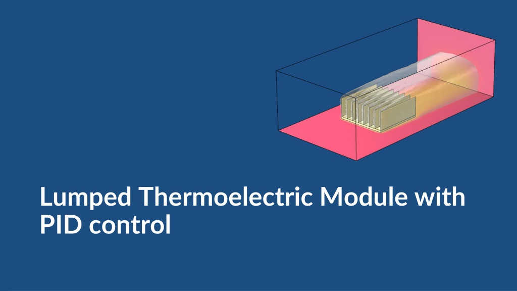
Model Definition An electronic device is connected to a thermoelectric module (TEM) via a contact element. On the other side, the TEM is connected to a heat sink. Fluid domain Heat sink fins Heat sink base A nonisothermal fluid flow is considered around the heat sink. Thermoelectric module Contact element The TEM is modeled with the Lumped Thermal System physics interface. Electronic device The heat sink fins are modeled as shells. Model geometry Only half of the actual geometry is shown
Model Definition The air velocity is set to 0.5 m/s at the inlet. Outlet Slip wall Interior walls Side and top boundaries of the fluid domain are slip walls, while the bottom one is a no slip wall. Thermoelectric module The electronic device generates 4 W of heat power. U0 = 0.5 m/s P = 4 W The TEM has a linear behavior: Wall Maximum current: 4 A Maximum heat rate: 40 W Maximum temperature difference: 70 C Resistance: 2 Model boundary conditions Only half of the actual geometry is shown
Results A parametric sweep of the current through the TEM is performed in a stationary study. The behavior of the system deviates from the linear TEM model because the heat sink also exchanges heat with the exterior air. For a current of 2 A, the device temperature is about 6.5 C, the heat rate of the TEM about 8 W and the temperature difference 28 C. Results of the stationary study Heat rate and temperature of the system for different intensities
Results In a second (transient) study, a PID controller is added to the model to stabilize the temperature of the electronic device to 6.5 C. The device is initially at ambient temperature, and starts generating heat after 10 min. The response of the system is evaluated. The steady state is reached after 1 h. The temperature of the device is quickly stabilized. After 1 h, the temperature difference is 28 C and the heat rate is 8 W, as predicted by the stationary study. Results of the transient study Heat rate and temperature of the system over time
Results At steady state, the current through the TEM is 2 A. The stationary computation accurately predicts the steady-state solution, while the transient computation allows to study the response of the system. Results of the transient study Heat rate and intensity through the system over time
