Understanding Electrical Wiring Systems and Their Importance

Electrical wiring systems consist of insulated conductors that supply power to various appliances in homes and buildings. The selection of wires is crucial based on factors like current rating, cost, and application. Different types of wiring exist for domestic, commercial, and industrial purposes, each with specific considerations. It is essential to ensure durability and safety in wiring installations to protect against hazards and ensure long-term functionality.

Download Presentation

Please find below an Image/Link to download the presentation.
The content on the website is provided AS IS for your information and personal use only. It may not be sold, licensed, or shared on other websites without obtaining consent from the author. Download presentation by click this link. If you encounter any issues during the download, it is possible that the publisher has removed the file from their server.
E N D
Presentation Transcript
Electrical wiring is generally refers to insulated conductor used to carry currentand associateddevice. Domestic electric appliances like lights, fans, washing machines, water pumps etc are connected to the supply through insulated wires which are controlled byswitches. The wiring diagram gives the connections of different appliances to the supplywithina house orbuilding.
State electricity board provide electric supply up to a point outside the consumer premises. From this point consumer take the connection to his main board . Insulated electrical wires will be taken out to various places in the permises to supply power to different type of loads like lights , fans , refrigerators , room coolers , heaters,etc.
The conductor material, insulation , size and the number of cores, specifies the electrical wires. The conductors are usually of either copper or aluminium. Various insulating materials like PVC,TRS and VIR are used. The wire may be of single strand or multi strand. Wires with combination of different diameters and the number of cores or strands are available.
The selection of the wire is made depending on the requirement considering factors like current and voltage ratings, cost and application. The current carrying capacity depends on the total area of the wires.
Wires are drawn along the consumers building to distribute power to all points where load is situated. Types of wiring according to uses; 1. Domesticwiring. 2. Commercial wiring. 3. Industrial wiring.
1. life of installation 2. future extension or alterations 3. construction of building 4. fire hazards or other special conditions 5. corrosive fumes 6. dampness 7. type of wire and material used 8. nature of load (lighting of power) 9. safety of the system 10. cost of wiring system
Durability : Type of wiring selected shouldconform to standard specifications, so that it is durable i.e. without being affected by the weather conditions, fumesetc. Safety : The wiring must provide safety against leakage, shock and fire hazards for the operating personnel. Appearance : Electrical wiring should givean aesthetic appeal to the interiors. Cost: It should not be prohibitivelyexpensive.
Accessibility : The switches and plug points provided should be easily accessible. There must be provision for further extension of the wiring system, if necessary. Maintenance Cost : The maintenance costshould be a minimum. Mechanical safety : The wiring must be protected against any mechanicaldamage.
These are the following types of wiring are:- 1. Cleat wiring 2. Wood casting wiring 3. CTS wiring or TRS wiring or Batten wiring 4. Conduit wiring 5. Metal sheathed wiring or lead sheathed wiring
In this type of wiring , wood or plastc cleats are fixed to walls or cellings at regular intervals .i.e.,0.6m between each cleat. PVC insulated cables are taken through the holes of each cleat . Cleat support and hold wires. This is cheap method . Is used for temporary installations. It is not suitable for home . It is outdated method.s
This System uses insulated Cables sub protected in porcelain cleats.
In this cable is run through a wood casing having grooves. The wood casing is of required fixed length with parallel grooves that accommodates thecables. The wooden casing is fixed to the walls or ceiling with screws. After placing the cables inside the grooves of casing , a wooden cap with grooves is placed on it to cover the cables. This is also cheap wiringsystem. There is a high risk of fire in case of shortcircuits.
In this , insulated wires are run through the straight teak wooden battens. The wooden battens are fixed on the ceiling or walls by plugs and screws. The cables are fitted onto the battens by using tinned brass link clips. These clips are fixed to the battens with rust-resistance nails. This wiring installation is simple and cheap. This system takes less time to install. These are mainly used for indoor installations
In this wiring , PVC cables are taken through either PVC conduit pipes or through steel conduit pipes. This conduit wiring can be either surface conduit wiring or concealed conduit wiring. If the conduits are run inside the surface of the walls and ceilings and are covered with plastering, it is called as conduit wiring.
Surface conduit wiring is used in industries to connect the heavy motors. Concealed wiring is the most popular and common method of wiring the residential buildings. This method is the safest method of wiring and also look beautiful.
Electrical drawings plays an important role in electrical installation works that they convey information about connection of various devices and equipments with mains. It provides the complete information,and also helps to assemble the various equipments.
It is a functional drawing which shows and describes the main operating principles of the equipments or devices. It consists of :- -principle functions (represented by blocks) - line connections (shows relationship between them). The diagram is usually drawn before implementing a circuit diagram.
Not give any detailed information. leaves the information about smaller cmponents.
Is a simplified notation ofan electrical system. Called as one-line diagram or single line diagram. Similar to the blockdiagram It consists of symbols to represent thecomponents. Lines to represent the wires or conductors which connects the components together. the line diagram isderived from the block diagram.
Electrical circuit is graphically represented in a simplifiedmanner. it gives the position information of various elements (in cm or m or mm) Doesn t give any layout of the parts and their detail wiring information of the components.
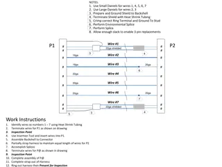
Wiring diagram is a representation of the circuit , shows the wiring between parts or elements. Gives detailed information about wiring . It includes:- -relative position -arrangement of devices -terminals on the devices It shows power supplies and earth connections .