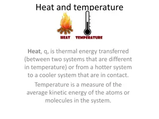
Understanding Heat Exchangers in Food Operations and Equipment
Explore the world of heat exchangers used in food operations, including pasteurization, blanching, evaporation, drying, sterilization, freezing, and extrusion. Learn about different types of heat exchange equipment such as double tube heat exchangers, shell and tube heat exchangers, and plate heat exchangers. Discover the principles of heat exchangers and their classifications based on the type of medium used and flow direction.

Download Presentation

Please find below an Image/Link to download the presentation.
The content on the website is provided AS IS for your information and personal use only. It may not be sold, licensed, or shared on other websites without obtaining consent from the author. Download presentation by click this link. If you encounter any issues during the download, it is possible that the publisher has removed the file from their server.
E N D
Presentation Transcript
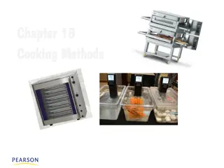
Heating and cooling are common in food operations Pasteurization Blanching Evaporation Drying Sterilization Freezing Extrusion
Heat exchangers Contact type Steam infusion Steam injection Non contact type Tubular Shell and Tube Plate Scraped Surface
HE classification: type of medium used Gas-Gas Liquid-Gas Liquid-liquid HE classification: flow direction Countercurrent . Concurrent (parallel). Countercurrent is more used than concurrent due to its higher efficiency.
Examples of heat exchangers Shell and tube heat exchangers : Surface Condenser.png
Plate thickness is 0.4 to 0.8 mm Channel lengths are 2-3 meters Plates are available in: Stainless Steel, Titanium, Titanium-Palladium, Nickel PLATES
One example of this type is the Double pipe heat exchanger. In this type, the hot and cold fluid streams do not come into direct contact with each other. They are separated by a tube wall or flat plate.
Principle of Heat Exchanger First Law of Thermodynamic: Energy is conserved. 0 0 0 0 dE = out h . out + + + h . m m q w e in s generated dt in = . h p . . q m C T h h h in out . . = m h m h = . c p C . q m T c c c Control Volume COLD HOT Thermal Boundary Layer Cross Section Area
THERMAL Region III: Solid Cold Liquid Convection BOUNDARY LAYER Energy moves from hot fluid to a surface by convection, through the wall by conduction, and then by convection from the surface to the cold fluid. NEWTON S LAW OF CCOLING dqx=hc. Tow Tc ( ).dA Th Ti,wall To,wall Tc Region I : Hot Liquid- Solid Convection Q hot Q cold NEWTON S LAW OF CCOLING dqx=hh. Th Tiw ( ).dA Region II : Conduction Across Copper Wall dqx= k.dT dr FOURIER S LAW
U = The Overall Heat Transfer Coefficient [W/m.K] ( ).A qx qx=hhot.Th Tiw Th Tiw= hh.Ai Region I : Hot Liquid Solid Convection r . ln q o x r 2 . r o k L copper = ( ) q T T = i Region II : Conduction Across Copper Wall T T x ln , , o wall i wall 2 . k L r i copper qx To,wall Tc= qx= hcTo,wall Tc ( )Ao Region III : Solid Cold Liquid Convection hc.Ao + lnro kcopper.2 L+ qx Th Tc= ri 1 1 R1+ R2+ R3 Th Tc=qx + hh.Ai hc.Ao ( ) qx=U.A. Th Tc 1 r . ln r o o r 1 r 1 + r r U = = + i r o U A. R i o . . h r k cold h hot i copper i
Calculating U using Log Mean Temperature C m dq . = = Cold Stream: ) = ( d T dT dT h p dT . Hot Stream : dq dq h c = h h h T hT T = h c ( ) d T c h p c p C . C . m m c p C . dT . dq m h c c c c = = = . dq dq dq dA T . . 1 1 = . + hot U cold ( ) dA . d T U T h p c p C . C . m m dq h c . q q T ( ) T T d T T A = + 2 2 . h c U dA T A 1 1 h c . T ( ) 1 1 d T T A = + 2 2 . U dA h p c p . . m C m C T A 1 1 h U c ( ) ( ) . . . T U A A ( ) = + = in h out h T in c out c T 2 ln T T T T h c T q q 1 T T T = . 2 1 q U A ln 2 T Log Mean Temperature 1
Log Mean Temperature evaluation ( ) ( . ) h p . c p C . . C . . m T T m T T T T T 3 6 7 10 h c = = = U 2 1 TLn A T A T ln 2 Ln Ln T 1 CON CURRENT FLOW 1 2 T1 Wall T2 A A T10 T2 T1 T4 T5 T6 T3 = = in h in c T T T T T 1 3 7 T9 = = T8 out h out c T T T T T 2 6 10 T7 Para llel Flow
Log Mean Temperature evaluation ( ) ( . ) h p . c p C . . C . . m T T m T T T T T 3 6 7 10 h c = = = U 2 1 TLn A T A T ln 2 Ln Ln T 1 COUNTER CURRENT FLOW 1 2 T3 T4 T6 T6 T1 Wall T2 T7 T8 T9 T10 A T10 T2 T1 T4 T5 T3 T6 = = in h out c T T T T T T9 T8 T7 1 3 7 Counter - Current Flow = = out h in c T T T T T 2 6 10
Heat Exchangers: The Effectiveness NTU Method
General Considerations Computational Features/Limitations of the LMTD (log mean Temperature difference) Method: The LMTD method may be applied to design problems for which the fluid flow rates and inlet temperatures, as well as a desired outlet temperature, are prescribed. For a specified H.E. type, the required size (surface area), as well as the other outlet temperature, are readily determined. If the LMTD method is used in performing calculations for which both outlet temperatures must be determined from knowledge of the inlet temperatures, the solution procedure is iterative. For both design and performance calculations, the effectiveness-NTU method (Number of Transfer Units) may be used without iteration.
Definitions Heat exchanger effectiveness, ? ( ratio between actual and max heat transfer) : q = max q 0 1 Fluid Heat Capacity Rates = = C m c C m c , , c c p c h h p h New Definitions: = min( , ) C C hC Max possible heat transfer min c = * ( ) q C T T max min , , h i c i
Maximum possible heat rate: ( ) = max q C T T min , , h i c i if C C C h h c = or C C min if C C c c h Why is Cminand not Cmax used in the definition of qmax? to include maximum feasible heat transfer among the working fluids during calculation Will the fluid characterized by Cmin or Cmax experience the largest possible temperature change through the HX?
Heat exchanger effectiveness * ( ) * ( ) C T T C T T q = = , , , , h h T i h T o c c T o c i * ( ) * ( ) q C C T max min , , min , , h i c i h i c i = * * ( ) q C T T min , , h i c i
Number of Transfer Units, NTU: UA C NTU min with q NTU A dimensionless parameter whose magnitude influences H.E. performance:
Effectiveness NTU Method C = ( , ) min f NTU C C min max C max ? ? UA NTU NTU C min
Effectiveness NTU Method For Parallel Flow with Cmin = Ch ( ) T T = , , h i h o ( ) T T , , h i c i m c ( ) T ( T C , h p h , , = = = c o c i min C r ) C T T m c max , , h i c i , c p c + 1 exp[ 1 ( )] NTU + 1 C = r C r
Effectiveness NTU Method For Parallel Flow with Cmin = Ch + 1 exp[ 1 ( )] NTU + 1 C = r C r 1 1 ( + ln[ 1 )] C = r NTU + C r
Effectiveness NTU Method For Counterflow with Cr = Cmin/Cmax 1 exp[ C 1 ( )] NTU C = 1 C r C r 1 exp[ 1 ( )] NTU r r NTU + = 1 C =1 r NTU
Effectiveness NTU Method For Counter-flow with Cr = Cmin/Cmax 1 1 = 1 C ln( ) NTU r 1 1 C C r r = 1 C =1 NTU r
Design Calculations: = ( ) , / NTU f C C min max Relations Table 11.4 or Figs. 11.14 - 11.19 For all heat exchangers, with C r For Cr = 0, (phase change: condensation or evaporation) to all HE types. a single relation applies NTU ( ) = 1 exp NTU or ( ) = 1n 1 NTU Performance Calculations: f NTU C = ( ) , / C min max Cr Relations Table 11.3 or Figs. 11.14 - 11.19
Effectiveness NTU Method Graphical Representations of Equations in Tables 11.3 & 11.4
Heat exchanger selection. Thermal performance analysis (NTUs) for co- & counter-current exchangers. Multi-pass exchangers (S&T). Condensation & boiling. Radiation.
General Procedure Must calculate heat duty Minimise cost subject to constraints fluid inlet and outlet temperatures allowable pressure drops compatibility of materials (corrosion) and fluids (direct/indirect contact) maintenance (repairs) availability (can we get it easily?) sensitivity to other conditions
General Considerations Design pressures Design temperatures Heat duty / size range Fluid type / compatibility Boiling/condensation ( quality ) Temperature driving forces Allowable pressure drops Fouling tendency Space limitations
Fundamentals of Heat and Mass Transfer THEODORE L. BERGMAN, FRANK P. INCROPERA, ADRIENNE S. LAVINE, DAVID P. DEWITT http://books.google.com.sa/books?hl=ar&lr=&id=vvyIoXEywMoC&oi=fnd&pg=PR21&dq=table+11.3+heat+exchanger+effectiveness+relations&ots=8HqjQScVI8&sig=eA2YjAcHwA8A1ls- CFT6RNEU8hY&safe=on&redir_esc=y#v=onepage&q=table%2011.3%20heat%20exchanger%20effectiveness%20relations&f=false