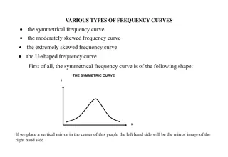
Geometric Design of Highway Vertical Curves and Criteria
This content covers the vertical alignment in transportation engineering, focusing on the geometric design of highway facilities, specifically vertical curves like crest and sag curves. It explains the main design criteria for vertical curves, including minimum stopping sight distance provision, drainage considerations, and driver comfort. The content also details criteria for crest and sag vertical curves lengths based on sight distances, with specifications for driver visibility and comfort, control of drainage, and overall appearance of the highway. Detailed formulas and considerations are provided for calculating and designing vertical curves according to safety and operational standards.

Download Presentation

Please find below an Image/Link to download the presentation.
The content on the website is provided AS IS for your information and personal use only. It may not be sold, licensed, or shared on other websites without obtaining consent from the author. Download presentation by click this link. If you encounter any issues during the download, it is possible that the publisher has removed the file from their server.
E N D
Presentation Transcript
CE 34500 Transportation Engineering Chapter 15: Geometric Design of Highway Facilities 1
Vertical Curves Main Design Criteria o Crest & Sag Vertical Curves Provision of minimum stopping sight distance o Sag Vertical Curves Adequate drainage Comfortable in operation Apprearance
Vertical Curves Two cases for minimum length based on sight distance o Sight distance is less than the length of the vertical curve (S < L) o Sight distance is greater than the length of the vertical curve (S > L) Must make assumption about which case is true and then check your assumption o Use of S < L criteria for design results in conservative (longer) vertical curve lengths
Crest Vertical Curve One criteria for length o Sight distance: Vertical curve must be long enough so that driver can see far enough ahead (stopping sight distance) to react and stop before striking an object in roadway Eye height = 3.5 ft. Object height = 2.0 ft.
Crest Vertical Curves 2 AS = (for S L) L ( ) min 2 + 200 H H 1 2
Crest Vertical Curves ( ) 2 + 200 H H = 1 2 2 (for S L) L S min A
Sag Vertical Curve Four criteria for length o Sight distance provided by the headlight beam is >= Stopping sight distance Headlight height = 2.0 ft. Upward divergence of headlight beam = 1o o Driver comfort: Radial acceleration <= 1 ft/sec2 o Control of drainage: Almost flat spot not too long o General appearance: Vertical curve doesn t look like a kink
Sag Vertical Curve + + 200( tan ) (400 3.5 ) A H S S = = 2 2 (for S L) L S S A H=2 = 1 degree 2 2 AS + AS + = = (for S L) L 200( tan ) (400 3.5 ) H S S
Sag Vertical Curve Comfort Criterion 2 Au L = 46 5 .
Sag Vertical Curve Drainage Criterion o Use when road has curbs o Maximum length instead of minimum Almost flat spot : Minimum grade of 0.35% provided within 50 ft of the level point K <= 167
Sag Vertical Curve Appearance Criterion = 100 L A o Per AASHTO Green Book for Sag and Crest Vertical Curves: LMIN (ft) = 3 x Design Speed (mph)
Crest & Sag Vertical Curve K is length of vertical curve per % change in A L =KA min K values for crest vertical curves for a given design speed found in Table 15.4 K values for sag vertical curves for a given design speed found in Table 15.5
Crest & Sag Vertical Curve
Vertical Curve Elevations Vertical curves are parabolas with origin at BVC o General form of a parabola: y = c + bx + ax2 Vertical curve fomula: o y = yBVC + G1 * x + a * x2 o a = ( G2 - G1 ) / ( 2 * L) o High or low point: dy/dx = 0
Vertical Curve Elevations Determine the minimum length of curve to satisfy sight distance requirements (and other requirements, if desired). Determine from the plan sheet the station and elevation of the PVI that is, the point where the grades intersect and the grades on either side of the PVI are given, Compute the elevations of the BVC and EVC. Compute elevations on the curve, usually 100 ft. apart at even stations, beginning with the first whole station after the BVC. If necessary, compute station and elevation of high or low point. 1. 2. 3. 4. 5.
Vertical Curves A Offset from tangent elevation Y = 2 x 200 L 100 G G LG L G = = x 1 1 G Distance from BVC ( ) ( ) (or l ow) high 100 G 1 2 1 2 2 LG G = 1 high Y 1 Offset from BVC Elevation ( ) (or low) 200 G 1 2
Example 15.3 A sag vertical curve is to be designed to join a -5% grade to a +2% grade. If the design speed is 40 mph, determine the minimum length of the curve that will satisfy all criteria. Assume a = 11.2 ft/sec2 and perception-reaction time = 2.5 sec.
Example 15.4 A crest vertical curve joining a +3% and a -4% grade is to be designed for 75 mph. If the tangents intersect at station (345+60.00) at an elevation of 250 ft, determine the stations and elevations of the BVC and EVC. Also, calculate the elevations of intermediate points on the curve at the whole stations. A sketch of the curve is shown in Figure 15.16.
Example 15.5 A sag vertical curve joins a -3% grade and a +3% grade. If the PVI of the grades is at station (345+50) and has an elevation of 235 ft, determine the station and elevation of the BVC and EVC for a design speed of 70 mph. Also, compute the elevation on the curve at 100-ft intervals. Figure 15.17 shows a layout of the curve.