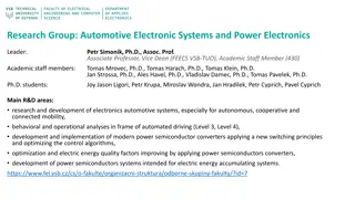
Analogue Electronics Course Overview at University of Diyala - Hayder Khaleel AL-Qaysi
Explore the comprehensive syllabus of the Analogue Electronics course offered in the Department of Electronic Engineering at University of Diyala. Lectured by Hayder Khaleel AL-Qaysi, topics covered include Introduction to Electronics, Diodes, Bipolar Junction Transistors (BJTs), Power Amplifiers, and more. Gain insights into amplifier frequency response, thyristors, Field-Effect Transistors (FETs), and Operational Amplifiers. Recommended textbooks and key references are also provided.
- Analogue Electronics
- University of Diyala
- Hayder Khaleel AL-Qaysi
- Electronic Engineering
- Course Overview

Download Presentation

Please find below an Image/Link to download the presentation.
The content on the website is provided AS IS for your information and personal use only. It may not be sold, licensed, or shared on other websites without obtaining consent from the author. Download presentation by click this link. If you encounter any issues during the download, it is possible that the publisher has removed the file from their server.
E N D
Presentation Transcript
University of Diyala College of Engineering Department of Electronic Engineering Analogue Electronics (Second Year) Lecturer: Hayder Khaleel AL-Qaysi
Contents First Semester: Introduction to Electronics The atom, materials used in electronics, current in semiconductors, N-Type and P-Type semiconductors, the PN Junction. Diodes and Applications Diode operation, voltage-current (V-I) characteristics, diode models, half-wave rectifiers, full- wave rectifiers, power supply filters and regulators, diode limiters and clampers, voltage multipliers. Special-Purpose Diodes The zener diode, zener diode applications, the varactor diode, optical diodes, other types of diodes. Bipolar Junction Transistors (BJTs) Bipolar junction transistor (BJT) structure, basic BJT operation, BJT characteristics and parameters, The BJTas an amplifier, the BJTas a switch, the phototransistor, transistor categories and packaging. Transistor Bias Circuits The DC operating point, voltage-divider bias, other bias methods. BJT Amplifiers Amplifieroperation,transistorAC models, thecommon-emitter amplifier,the common-collector amplifier, the common-base amplifier, multistage amplifiers, the differential amplifier. Second Semester: Power Amplifiers The classApower amplifier,the class B and classAB push-pull amplifiers,theclass C amplifier. Field-Effect Transistors (FETs) The JFET, JFET characteristics and parameters, JFET biasing, the ohmic region, the MOSFET, MOSFET characteristics and parameters, MOSFET biasing, the IGBT. FET Amplifiers and Switching Circuits The common-source amplifier, the common-drain amplifier, the common-gate amplifier, the class D amplifier, MOSFET analog switching, MOSFET digital switching. 1
Amplifier Frequency Response Basic concepts, the decibel, low-frequency amplifier response, high-frequency amplifier response, total amplifier frequency response, frequency response of multistage amplifiers. Thyristors The four-layer diode, the silicon-controlled rectifier (SCR), SCR applications, the diac and triac, the silicon-controlled switch (SCS), the unijunction transistor (UJT), the programmable unijunction transistor (PUT). The OperationalAmplifier Introduction to operational amplifiers, Op-Amp input modes and parameters, negative feedback, Op-Amps with negative feedback, effects of negative feedback on Op-Amp impedances, bias current and offset voltage, open-loop frequency and phase responses, closed-loop frequency response. Textbook: Thomas L. Floyd, Electronic Devices: Electron Flow Version, 9th edition, Pearson Education, Inc., Upper Saddle River, New Jersey, 2012. References: 1. R. Boylestad., and L. Nashelsky, Electronic Devices and Circuit Theory. 11th edition, Pearson Education Limited, London, 2014. 2. Horowitz and Hill,TheArt of Electronics, 2nd edition,Cambridge UniversityPress, 1989. 3. A. Malvino, and D. J. Bates, Electronic principle, McGraw Hill, 7th edition, 2005. 2
Lecture 1: Introduction to Electronics Electronic devices such as diodes, transistors, and integrated circuits (ICs) are made of a semiconductive material. To understand how these devices work, we should have a basic knowledge of the structure of atoms and the interaction of atomic particles. An important concept introduced in this lecture is that of the pn junction that is formed when two different types of semiconductive material are joined. 1.1 The Atom According to the classical Bohr model, the atom is viewed as having a planetary-type structure with electrons orbiting at various distances around the central nucleus, as illustrated in Figure 1-1. The nucleus of an atom consistsof protons and neutrons.The protons have a positivecharge and the neutrons are uncharged.The number of protons is the atomic number of the atom. Electrons have a negative charge and orbit around the nucleus at distances that depend on their energy level. An atom has discrete bands of energy called shells in which the electrons orbit. Atomic structure allows a certain maximum number of electrons in each shell and is a fact of nature and can be calculated by Equation (1-1). In their natural state, all atoms are neutral(an electricallybalanced)because theyhave an equal number ofprotonsand electrons. ?= 2?2 Equation 1-1 where n is the number of the shell. The outermost shell or band of an atom is called the valence band, and electrons that orbit in this band are called valence electrons. These electrons have the highest energy of all those in the atom. If a valence electron acquires enough energy from an outside source such as heat, it can jump out of the valence band and break away from its atom. This is the basis for conduction in materials. FIGURE 1-1: The Bohr model of an atom showing electrons in orbits around the nucleus, which consists of protons and neutrons. The tails on the electrons indicate motion. 3
1.2 Materials Used in Electronics Materials can be classified in terms of their electrical properties into three groups: conductors, semiconductors, and insulators. When atoms combine to form a solid, crystalline material, they arrange themselves in a symmetrical pattern. The atoms within the crystal structure are held together by covalent bonds, which are created by the interaction of the valence electrons of the atoms. Insulators: insulators (Insulating materials) have very few free electrons and do not conduct electrical current at all under normal conditions. Examples of insulators are rubber, plastics, glass, mica, and quartz. Conductors: materials that are conductors have a large number of free electrons and conduct electrical current very well. Examples of conductors are copper (Cu), silver (Ag), gold (Au), and aluminum (Al). Semiconductors: semiconductive materials fall in between conductors and insulators in their ability to conduct electrical current. Examples of semiconductors are antimony (Sb), arsenic (As), astatine (At), boron (B), polonium (Po), tellurium (Te), silicon (Si), germanium (Ge), gallium arsenide, indium phosphide, gallium nitride, silicon carbide, and silicon germanium. Semiconductor atoms have four valence electrons. Silicon is the most widely used semiconductive material. Semiconductoratoms bondtogetherinasymmetrical patterntoformasolidmaterial called a crystal. The bonds that hold a crystal together are called covalent bonds. Figure 1-2 shows energy diagrams for insulators, semiconductors, and conductors. FIGURE 1-2: Energy diagrams for the three types of materials. 4
1.3 Current in Semiconductors The valence electrons that manage to escape from their parent atom are called conduction electrons or free electrons. They have more energy than the electrons in the valence band and are free to drift throughout the material. When an electron breaks away to become free, it leaves a hole in the valence band creating what is called an electron-hole pair. This is illustrated in the energy diagram of Figure 1-3(a) and in the bonding diagram of Figure 1-3(b). Theseelectron-holepairs arethermallyproducedbecausetheelectronhas acquiredenough energy from external heat to break away from its atom. A free electron will eventually lose energy and fall back into a hole. This is called recombination. Electron-hole pairs are continuously being thermally generated so there are always free electrons in the material. When a voltage is applied across the semiconductor, the thermally produced free electrons move toward the positive end and form the current. This is one type of current and is called electron current. Another type of current is the hole current. This occurs as valence electrons move from hole to hole creating, in effect, a movement of holes in the opposite direction. FIGURE 1-3: Creation of electron-hole pairs in a silicon crystal. Electrons in the conduction band are free electrons. 5
1.4 N-Type and P-Type Semiconductors An n-type semiconductivematerial is created byadding impurityatoms that have fivevalence electrons, as illustrated in Figure 1-4. These impurities are pentavalent atoms. Because the pentavalent atom gives up an electron, it is often called a donor atom. Ap-typesemiconductoris createdbyaddingimpurityatoms withonlythreevalenceelectrons, as illustrated in Figure 1-5. These impurities are trivalent atoms. Because the trivalent atomcan take an electron, it is often referred to as an acceptor atom. The process of adding pentavalent or trivalent impurities to a semiconductor is called doping. The majority carriers in an n-type semiconductor are free electrons acquired by the doping process, and the minority carriers are holes produced by thermally generated electron-hole pairs. The majority carriers in a p-type semiconductor are holes acquired by the doping process, and the minority carriers are free electrons produced by thermally generated electron-hole pairs. FIGURE 1-4: Pentavalent impurity atom in a silicon crystal structure. An antimony (Sb) impurity atom is shown in the center. The extra electron from the Sb atom becomes a free electron. FIGURE 1-5: Trivalent impurity atom in a silicon crystal structure. A boron (B) impurity atom is shown in the center. 6
1.5 The PN Junction Apn junction is formed when part of a material is doped n-type and part of it is doped p-type. A depletion region forms starting at the junction that is devoid of any majority carriers, as indicated in Figure 1-6(a). The depletion region is formed by ionization, as indicated in Figure 1-6(b). The barrier potential is typically 0.7 V for a silicon diode and 0.3 V for germanium. FIGURE 1-6: Formation of the depletion region. 7