Further Discussion on Non-primary Channel Access in IEEE 802.11
This contribution delves into the utilization of non-primary channels for access in IEEE 802.11 networks, focusing on enhancing frequency reuse, adhering to ETSI standards, evaluating CCA capability types, and analyzing non-ideal deployment scenarios. It discusses the complexity and benefits of non-primary channel access, addressing challenges such as bandwidth efficiency and power consumption through potential solutions like Dynamic Subband Operation and non-AP power save features.

Download Presentation

Please find below an Image/Link to download the presentation.
The content on the website is provided AS IS for your information and personal use only. It may not be sold, licensed, or shared on other websites without obtaining consent from the author. Download presentation by click this link. If you encounter any issues during the download, it is possible that the publisher has removed the file from their server.
E N D
Presentation Transcript
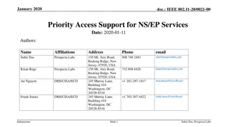
doc.: IEEE 802.11-23/2023r0 November 2023 Further discussion on Non-primary Channel Access Date: 2023-11-14 Authors: Name Affiliations Address Phone Email Sindhu Verma sindhu.verma@broadcom.com Shubhodeep Adhikari shubhodeep.adhikari@broadcom.com Broadcom Matthew Fischer matthew.fischer@broadcom.com Vinko Erceg vinko.erceg@broadcom.com Submission
Introduction This contribution is a follow-up of the contributions 11-23/0034r1, 11-23/1288r0 and 11-20/0363r3 which proposed non-primary channel access for 11bn and 11be respectively. It contains the following: Discussion of a frequency reuse 1 configuration that can be enabled by non-primary channel access even in dense enterprise deployments. Adherence of NPCA to the ETSI harmonized standards for 5GHz and 6GHz Further analysis of the potential CCA capability types for devices that perform non-primary channel access. The capability types are defined as Type 0, Type 1, Type 2 and Type 2+. We discuss the complexity of implementation as well as their performance, resolution of corner cases, fairness towards legacy devices and scalability. Evaluation of non-primary channel access in a non-ideal configuration. This configuration consists of 20 apartments in a 2x10 configuration in a single floor. It is the single floor version of the 11ax Residential scenario. Submission Slide 2
A frequency-reuse 1 deployment enabled by NPCA (1) Different generations of 802.11 have defined channels with successively wider bandwidths: 20MHz 40MHz - 80MHz - 160MHz - 320MHz. This has exacerbated the problem of channel access in 802.11, where a single busy primary 20MHz channel can block access to the entire wider bandwidth, even if the non-primary portions of the bandwidth are idle. To work around this problem, managed 802.11 deployments usually split the available bandwidth into narrower bandwidths with different primary channels and allocate different BSSs to these narrower bandwidths. Such frequency planning is complex. It is also inefficient. For example, an application within a BSS is only able to use the narrower bandwidth of the BSS and not anything wider, even if spare adjacent bandwidth is available in other BSSs. Non-primary channel access can solve this problem cleanly for devices that are capable of such channel access. Such devices can all share the same primary within the widest possible bandwidth and opportunistically use any available bandwidth with or without the primary. - Submission Slide 3
A frequency-reuse 1 deployment enabled by NPCA (2) Such wideband frequency reuse 1 operation has the following challenges and solutions: Inefficiency due to the disparity in bandwidths supported by the AP and non-AP: For example, if there are many 80MHz clients in a 320MHz BSS, it could lead to wasting bandwidth whenever the AP is able to schedule only these narrower bandwidth capable clients in a PPDU/TXOP. This problem would be solved by a complementary feature, that of Dynamic Subband Operation ([5] and [6]). DSO will ensure that an AP is able to move narrower bandwidth clients to any part of the wider BSS bandwidth and thus efficiently pack the entire wider bandwidth. Increased non-AP power consumption due to listening on wideband channels: This problem too would be solved by a complementary feature on non-AP power save ([7] and [8]). This feature would allow a non-AP to listen on only 20MHz per link, with 1 NSS and low MCS. Any transmission by the AP to such a non-AP would be preceded by an Initial Control Frame (similar to EMLSR) that would provide the non-AP with information on the bandwidth, NSS and max MCS of the subsequent frame exchanges. Configurable padding in the ICF would also allow the non-AP to switch to the required bandwidth/NSS/max MCS capabilities after receiving the ICF. Submission Slide 4
NPCA and the ETSI harmonized standards for 5GHz and 6GHz (1) Some members have opined that NPCA may not adhere to the channel access procedures specified by the ETSI harmonised standards EN 301.893 and EN 303.687 for 5GHz and 6GHz respectively. They specifically point out that NPCA envisages the primary channel to be changed dynamically, while the ETSI harmonised standards do not allow such dynamic change for multi-channel access procedures that follow the 802.11 EDCA scheme (i.e. one that comprises of full EDCA backoff on one channel and PIFS CCA on the remaining channels): The primary operating channel is arbitrarily determined and not changed more than once per second. (section 4.2.7.3.2.3 of EN 301.893 and 4.3.6.3.2.3 of EN 303.687). However, NPCA does not require a device to dynamically change its primary channels. NPCA proposes that an AP and client negotiate multiple sets of channels (referred to as groups of adjacent channels in ETSI) where each set contains one primary channel; the sets of channels and the primary channel in each set are chosen semi-statically. Each primary channel say Piis contained in a set of channels Si: if EDCA succeeds on the primary channel Pi, PIFS CCA is performed on the remaining channels of Si. Submission Slide 5
NPCA and the ETSI harmonized standards for 5GHz and 6GHz (2) For example, if the total aggregate bandwidth is 160MHz and there is one additional anchor channel: There are two primary channels P1and P2; P1is the legacy primary channel and P2is the additional primary (i.e. anchor) channel. P1is associated with set S1that consists of 8 20MHz channels with a total bandwidth of 160MHz. If EDCA succeeds on P1, PIFS CCA is attempted on the remaining 7 channels. P2is associated with a set S2of 4 20MHz channels with a total bandwidth of 80MHz. If EDCA succeeds on P2, PIFS CCA is attempted on the remaining 3 channels. S2is a subset of S1 In addition, other procedures are defined to ensure that NPCA is fair to devices that implement legacy 802.11 and similar unlicensed channel access schemes, such as: A device attempts transmission on set S2only if the primary channel P1of set is S1busy and only for the duration the primary channel P1is estimated to be busy. Submission Slide 6
NPCA and the ETSI harmonized standards for 5GHz and 6GHz (3) STR, NSTR and EMLSR in 802.11be too allow multi-channel transmissions on multiple sets of channels S1, S2,...where each set Skhas its own primary (i.e. full EDCA) channel Pk. For STR, NSTR and EMLSR, the sets S1, S2.. are non-overlapping, while for NPCA they are overlapping. Similar multi-channel transmission on multiple sets of channels, where each set has its own primary-like channel is allowed for LAA and NR-U too. Reference: 3GPP TS 36.104 section 5.7.4, read along with 3GPP TS 37.213 section 4.1.6 and 3GPP TS 36.101 section 5.5A. Submission Slide 7
Capability types for performing CCA before transmission or for reception Type 0: As many decoders as the number of anchor channels. Can perform ED+PD on these multiple anchor channels even if the preambles of PPDUs on the different anchor channels overlap in time. Not much support for Type 0; so it is not included in the subsequent analysis. Type 1: Only 1 decoder that can be flexibly moved to any of the anchor channels based on LTF/STF detection Can perform ED on these multiple anchor channels in parallel Can perform PD or receive PPDUs on these multiple anchor channels one at a time based on LTF/STF detection on an anchor channel. Type 2: Only 1 decoder dedicated to 1 designated anchor channel at any time Can perform ED+PD or receive PPDUs only on the designated anchor channel Type 2+: An enhancement of Type 2 which is the same as Type 2 except that it can additionally perform ED on the multiple anchor channels in parallel Submission Slide 8
Summary of NPCU device capability types Capability Type Number of anchor channels 1 N 2 N 2+ N 1 ED+PD on 1 anchor channel and ED-only on the others 1 anchor channel at a time Number of anchor channels on which CCA can be performed N 2 Number of anchor channels on which 802.11 STF/LTF can be received 1 anchor channel at a time 1 anchor channel at a time All N channels 3 Flexibly on any 1 of the N anchor channels During decode on 1 anchor channel, decode pauses on others 1 anchor channel at a time and in an order negotiated between the NPCU receiver/ transmitter Number of anchor channels on which 802.11 L-SIG and other PHY headers can be received Same as 2 4 All N anchor channels in parallel 1 anchor channel at a time All N anchor channels in parallel Energy Detection on anchor channels 5 1 anchor channel at a time with the constraints in 4. 1 anchor channel at a time with the constraints in 4. Number of anchor channels on which NPCU receiver can receive PPDUs from an NPCU transmitter Any of the N anchor channels with the constraints in 4. 6 Submission Slide 9
Comparison between Type 1 and Type 2 (1) Capability type 1 2 2+ Preamble Decode (PD) on multiple anchor channels. This involves LTF-STF detection in parallel followed by switching of the decoder PD as well as Energy Detection (ED) on only 1 channel at any time which makes it the simplest PD on only one channel at a time but ED on multiple channels which is not as complex as PD 1 Complexity Missed preambles can lead to corner cases. However ED is as good as Type 2+ ED is more predictable, though it can only be done at a higher threshold than PD ED is more predictable, though it can only be done at a higher threshold than PD 2 Predictability Fairness can be questioned, as CCA on the remaining anchor channels use ED-only, which is expected to be at a higher threshold than PD Fair, as CCA ED+PD is likely to use the same thresholds as legacy or OBSS Fair, as CCA ED+PD is likely to use the same threshold as legacy or OBSS Fairness to legacy devices and OBSS 3 Submission Slide 10
Comparison between Type 1 and Type 2 (1) Present; as a Type 1 transmitter can do CCA on multiple anchor channels and a Type 1 receiver can detect PPDUs on multiple anchor channels Flexibility of the transmitter to use any available channel among the remaining anchor channels (when the current anchor channel is busy) Absent, as Type 2+ receiver can detect PPDUs only 1 channel at a time. Absent, as access occurs 1 channel at a time 4 For example, if one assumes the following: a) 3 non-primary anchor channels i.e. a total of 4 anchor channels b) p is the probability of accessing any anchor channel and c) probabilities of accessing these channels are independent, then: Total probability of Type 2+ access = [1- (1-p)2] Total probability of Type 1 access = [1 - (1-p)4] The ratio of the above Type 1 to Type 2+ access probabilities is [1+(1-p)2] which means that Type 1 provides a gain of (1-p)2over Type 2+. This is quite significant for lower values of p. For example, there is 49% gain if p is 0.3 and 25% gain if p is 0.5. Submission Slide 11
Comparison between Type 1 and Type 2 (2) Capability type 1 2 2+ More efficient as it can access any non-primary anchor channel that is available Less efficient as it can access only 1 designated non-primary anchor channel at any time An ordered way of accessing channels becomes cumbersome with multiple non-primary anchor channels Less efficient as it can access only 1 designated non-primary anchor channel at any time An ordered way of accessing channels becomes cumbersome with multiple non-primary anchor channels 5 Efficiency Scalable to any number of non- primary anchor channels 6 Scalability Submission Slide 12
Corner case scenarios for different NPCU capability types (1) Capability type 1 2 2+ If the decoder is currently on channel x, it decodes information only on x While decoding preamble or data on one anchor channel x, a preamble is also received on another anchor channel y Misses information on y while decoding information on x, if preambles on x and y overlap in time If the decoder is currently on channel x, it decodes information only on x 1 Can happen but only as a corner case, if the backoff has already expired on channel y or expires at the same time as the start of the preamble on channel x. This is because, decoding the preamble on one anchor channel makes the device unable to do PD on other anchor channels. In this case, the NPCU device needs to wait to resolve the contents of the reception on x as not for itself before resuming any action on the backoff expiry on y (along with any Medium Sync recovery, if needed) Can happen more frequently than Type 1 However, no action is possible for a Type 2+ NPCU transmitter on channel y unless channel y is next in order for transmission after channel x. In that case, the NPCU device needs to wait to resolve the contents of the reception on x as not for itself before resuming any action on backoff expiry on y A preamble or data reception occurs on one of the anchor channels x and the backoff expires on another anchor channel y Not possible 2 Submission Slide 13
Corner case scenarios for different NPCU capability types (2) Capability type 1 2 2+ Backoff expires on a non-primary anchor channel x while the primary channel is idle and its backoff hasn t expired, and then the primary channel becomes occupied Needs to redraw backoff counter on channel x to avoid collisions Not possible Same as Type 1 3 Clients may transmit including the primary channel but this can happen only in case of hidden nodes. MU-EDCA can prevent this from occurring for 11ax and later. Even if the client transmits, the primary channel is busy for the AP and this is no different from the legacy hidden node case A transmission is initiated by an AP on a non-primary channel x and a client transmits to the AP on the primary channel Same as Type 1 Same as Type 1 4 Submission Slide 14
Corner case scenarios for different NPCU capability types (3) Capability type 1 2 2+ Can only happen if the client is an NPCU capable 11bn device. It is a race condition as the NPCU AP will be able to see the NPCU transmission by the client on channel y if it occurs earlier or the NPCU client will be able to see the NPCU AP transmission on channel x if it happens earlier. MU-EDCA-like scheme can prevent this from occurring and is advisable for 11bn NPCU clients on non-primary channels. (MU-)RTS/CTS can also be used for additional protection The order of trying non- primary channels is preconfigured and hence, this occurs only in case there is a hidden node on one of the non- primary anchor channels. MU-EDCA can prevent this from occurring. (MU-)RTS/CTS can also be used for additional protection A transmission is initiated by an AP on a non-primary channel x and a client transmits to the AP on another non-primary channel y Same as Type 2 5 Submission Slide 15
Corner case scenarios for different NPCU capability types (4) Capability type 1 2 2+ Misses the information on primary channel while decoding information on x. Can be mitigated if channel x is looked at only if the primary channel is busy . The only corner case is where the OBSS which makes the primary channel busy for the NPCU receiver is hidden from the NPCU transmitter which thus observes the primary channel as idle. UHR specific headers can help reduce the probability of missing the primary channel decode by reducing the time spent on finding the preamble on x as not for itself As it is expected to decode information only on x at the given time, this is not possible except in case of hidden nodes in the same manner as described for Type 1. A preamble or data reception occurs on one of the anchor channels x and during it, a preamble for self also occurs on the primary channel Same as Type 2 6 As it is expected to decode information only on x at the given time, this is not possible except in case of hidden nodes in the same manner as described for Type 1. A preamble or data reception occurs on one of the anchor channels x and during it, a preamble for self also occurs on another anchor channel y Misses the information on y while decoding information on x. UHR specific headers can help reduce the probability of missing the preamble on channel y by reducing the time spent on finding the preamble on x as not for itself Same as Type 2 7 Submission Slide 16
Non-ideal evaluation scenario (1) The simulation topology is a 1-floor version of the 11ax Residential Scenario There are 20 apartments in the floor in a 2x10 configuration. Each apartment has a 10x10m rectangular layout. Each apartment has 1 randomly-placed AP on a 320 MHz link in 6GHz. Each AP has 1 to 4 clients placed randomly inside the apartment. APs have 320 MHz bandwidth and clients randomly selected bandwidths between 160/320 MHz DL only traffic (for now) AP txpower = 20 dBm and 5dB inter-apartment wall loss. Submission Slide 17
Non-ideal evaluation scenario (2) 1 client is always AC_BE with data rate fixed at (a) 200 Mbps, or (b) Full-buffer Remaining 0-3 clients randomly choose their flows from among the following 4 types: AR/VR (AC_VO with 120 FPS => data rate 200 Mbps) HD Voice (AC_VO with 120 bytes every 10ms => data rate 96Kbps) 4K Video streaming (AC_VI 60 FPS => data rate 20Mbps) Video conference (AC_VO with 60 FPS => data rate 6Mbps) Channel model CCA threshold: ED/PD -72dBm/-82dBm (configurable). MCS based on signal and interference, calculated using 11ax residential pathloss model. Static interference model. For any Tx-Rx pair, interference at Rx is the sum of the Tx power of every potential interferer (AP or non-AP) outside the CCA zone of the Tx Type 1 operation Submission Slide 18
Cumulative throughput over 20 apartments in the floor, for Full-buffer Best Effort traffic, in the absence of Low Latency traffic NPCA provides 60% throughput gain for a higher CCA threshold (i.e. ED = -72dBm PD = -82dBm) and 50% throughput gain for a lower CCA threshold (i.e. when ED = -82dBm PD = -82dBm). A higher CCA threshold results in substantially higher spatial reuse. The number of total TXOPs in the simulation or the number of parallel TXOPs at any time is about 30-40% higher in case of ED = -72dBm PD = -82dBm compared to ED = -82dBm PD = -82dBm, both without and with NPCA. However, the steady state MCSs are lower for a higher CCA threshold than for a lower CCA threshold. This offsets some of the spatial reuse gain and leads to a lower throughput gain Submission Slide 19
Cumulative throughput over 20 apartments in the floor, for Full-buffer Best Effort traffic in the presence of Low Latency traffic Observations on cumulative throughput and NPCA gain when LL traffic is present, are similar to the previous configuration when LL traffic is absent NPCA provides 70% throughput gain for a higher CCA threshold and 60% throughput gain for a lower CCA threshold. A higher CCA threshold results in a higher spatial reuse but also a lower average MCS of transmission. Resultantly, the cumulative throughput with ED -72dBm PD = -82dBm is slightly better than the cumulative throughput with ED = -82dBm PD = -82dBm. Submission Slide 20
AR/VR Latency in the presence of Full-buffer Best Effort traffic A higher CCA threshold provides higher spatial reuse, which is visible in the better latencies of ED -72dBm PD = -82dBm compared to ED -82dBm PD = -82dBm both without and with NPCA The higher opportunities using NPCA also get utilized by AR/VR and other finite rate traffic in a prioritized manner. However full buffer AC_BE traffic in every BSS results in high contention from every AP and hence, higher 99%ile latencies Overall, NPCA provides significant latency reduction over almost the entire range of latency percentiles. Submission Slide 21
AR/VR Latency in presence of 200Mbps Best Effort traffic Expectedly, AR/VR latencies are much lower in presence of 200Mbps AC_BE are much lower than in the presence of Full-Buffer AC_BE As in the previous configuration, NPCA provides significantly lower latencies over the entire range of latency percentiles Submission Slide 22
Latency for 200Mbps Best Effort traffic NPCA provides significant latency gains for Best Effort traffic over the entire range of latency percentiles Submission Slide 23
User Perceived Throughput (UPT) for 200Mbps Best Effort traffic NPCA provides significantly higher User Perceived throughput for Best Effort traffic Submission Slide 24
Conclusions NPCA can enable a frequency reuse 1 configuration even in dense enterprise deployments. This will simplify frequency planning in such deployments. It will also increase efficiency as NPCA capable devices can opportunistically use the widest possible bandwidth instead of being segregated into non- overlapping narrower bandwidth BSSs. NPCA adheres to the ETSI harmonized standards for 5GHz and 6GHz Discussion and analysis of different capability types possible for NPCA in terms of complexity, fairness, scalability and performance benefits. Discussion of various corner cases that can arise in NPCA for these capability types and the possible outcomes and corrective measures Simulation results for a single floor 20 apartment scenario based on the 11ax residential topology with multiple traffic types. Even in this topology, it is seen that NPCA provides significant benefits over legacy operation for both latency-sensitive and best effort traffic. Submission Slide 25
Reference [1] IEEE P802.11be /D4.1 [2] 11-23/0034r1 Non Primary Channel Utilization [3] 11-23/1288r0 Non Primary Channel Utilization Follow-up [4] 11-20/0363r3 Non Primary Channel Utilization [5] 11-22/2204r0 Dynamic Subband Operation [6] 11-23/2141r0 Further discussion on Dynamic Subband Operation [7] 11-23/1875r0 Power save proposal for non-AP/mobile-AP [8] 11-23/1873r0 Post-FCS MAC padding Submission Slide 26


")
")
")
")
")


")
")
")


")
")


 for 200Mbps Best Effort")