Understanding DC Bridge Circuits: Wheatstone and Kelvin Bridges
DC bridges such as the Wheatstone and Kelvin bridges are used to measure resistance values. The Wheatstone bridge consists of parallel resistance branches with a null detector to indicate balance, allowing calculation of unknown resistances. The Kelvin bridge is used for measuring low resistances. Both bridges work based on the principle of balancing voltage ratios to determine unknown values accurately.
Download Presentation

Please find below an Image/Link to download the presentation.
The content on the website is provided AS IS for your information and personal use only. It may not be sold, licensed, or shared on other websites without obtaining consent from the author. Download presentation by click this link. If you encounter any issues during the download, it is possible that the publisher has removed the file from their server.
E N D
Presentation Transcript
Chapter 04 DC BRIDGES 1
Summary 4.1 Fundamental concept of bridge circuit 4.2 Principle of DC bridge 4.2.1Wheatstone Bridge and application 4.2.2Kelvin Bridge 2
Fundamental Concept of Bridges Circuit Bridge - to measure unknown values of resistance - the bridge circuit works as a pair of two-component voltage dividers connected across the same source voltage, with a null-detector meter movement connected between them to indicate a condition of "balance" at zero volts - In a condition of balance; - or 3 1 R R R R= = R R R R 1 4 3 2 2 4 3
Principle of DC Bridges Type of DC Bridges 1. Wheatstone Bridges - used for the measurement of dc resistance 2. Kelvin Bridges - used for the measurement of low resistance 4
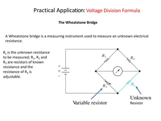
Wheatstone bridge - Consists of two parallel resistance branches - A voltage source is connected across the resistance network - A null detector, usually a galvanometer is connected between the parallel branches to detect a balanced condition R1 & R2 = precision resistors (standard) known R3 = adjustable resistor (precisely calibrated) - measured R4 / RX = unknown to be calculated 5
Wheatstone Bridge Initially, the bridge is in unbalanced condition; - galvanometer will give a reading (current flows through the galvanometer) - V2 Vx R3 is carefully adjusted so that no current will flow through the galvanometer - IG =0 & V2 =Vx the bridge is now in balanced condition From the figure, R 2 R + R + = = 2 x V V V V 2 S x S R R R 1 3 x In balanced condition, V2 = VS, hence, R1Rx = R2R3 So, R Rx = R 2 3 R 1 6
Wheatstone bridge The bridge is balance when no current through the Galvanometer (Ig =0) = = V V V V or BD CD AB AC R R + = 1 X E E + R R R R 3 + 2 1 + X = ( ) ( ) R R R R R R R 1 + 2 1 R 3 X X = + R R R R R R 1 2 1 1 3 X X X = R R = R R 2 1 3 X ( / ) R R R R 1 3 2 X 7
Example 1 Given value R1 = 1.5K , R2= 1K , R3= 3K & Rx= 2K . Prove the bridges in balance condition. Solution: The bridges in balance condition when: = k k k 3 3 ( The bridges is in balance condition) R 3 ( R R ) R 2 ( 3 2 1 x = M )( 1 5 . 1 )( ) k = M 8
EXAMPLE 2 Refer to figure below, calculate the Rx when the bridges balance. Solution : R = 3 R R 200 1 x R 2 200 800 = R x 750 800 = 213 33 . R x 750 9
Example 3 Calculate the value of unknown resistance at the Wheatstone bridge in Figure 3, assuming the bridge to be in balanced condition. Solution: R1= 2k , R2= 10k , R3= 5k , and R4 = Rx R 1 = R R R 4 2 3 R = 2 R R 3 x R 1 k 10 5 k 2 k = R x = 25 R k 10 x
Example 4 A Wheatstone bridge has R2 = 3.5 k , R3 = 5.51k and R1 = 7 k . (a) Calculate for Rx (b) Determine the measurement range if R3 is adjusted from 1 k - 8k Ans: (a) 2.755 k (b) 500 - 4 k 11
Example 5 1. Given the Wheatstone bridge with R1 = 15 k , R2 = 10 k , and R3 = 4.5 k . Find RX. 2. Calculate the current through the Galvanometer in the circuit. Given R1 = 1 k , R2 = 1.6 k , R3 = 3.5 k , R4 = 7.5 k , RG = 200 and V = 6V. Ans: 1. 3K , 2. 12
Kelvin Bridge a modification of Wheatstone s bridge also called a Kelvin double bridge and some countries Thomson bridge used to measure values of resistance below 1 In low resistance measurement, the resistance of the leads connecting the unknown resistance to the terminal of the bridge circuit may affect the measurement. 13
Bridge Balance Equation for Kelvin Bridge Ry - resistance of the connecting leads from R3 to Rx. Galvanometer can be connected either to point c or to point a. connected to point a, the resistance Ry, of the connecting lead is added to the indication for Rx. connection is made to point c, Ry is added to the bridge arm R3 - resulting measurement of Rx is lower than the actual value. (Actual value of R3 is higher than its nominal value by the resistance Ry) If the galvanometer is connected to point b, in between points c and a, in such a way that the ratio of the resistance from c to b and that from a to b equals the ratio of resistances R1 and R2, then 15
Bridge Balance Equation for Kelvin Bridge 16
Bridge Balance Equation for Kelvin Bridge 17
Example 5 If in Figure 5 the ratio of Ra to Rbis 1000 , R1 is 5 and R1 = 0.5R2. What is the value of Rx. Solution: R Rx= 1 R 3R 2 18
