Understanding Induction Motors: Construction and Characteristics
Induction motors are widely used in various applications due to their advantages like robustness, high power-to-weight ratio, and low cost. However, they have limitations such as fixed speed operation. These motors consist of a stationary stator and a rotating rotor, with different designs like squirrel cage and wound rotor. The stator provides the space for stator windings, while the rotor can be either conducting bars or a set of windings connected to slip rings. Understanding the construction and operation of induction motors is essential for electrical engineers and technicians.

Download Presentation

Please find below an Image/Link to download the presentation.
The content on the website is provided AS IS for your information and personal use only. It may not be sold, licensed, or shared on other websites without obtaining consent from the author. Download presentation by click this link. If you encounter any issues during the download, it is possible that the publisher has removed the file from their server.
E N D
Presentation Transcript
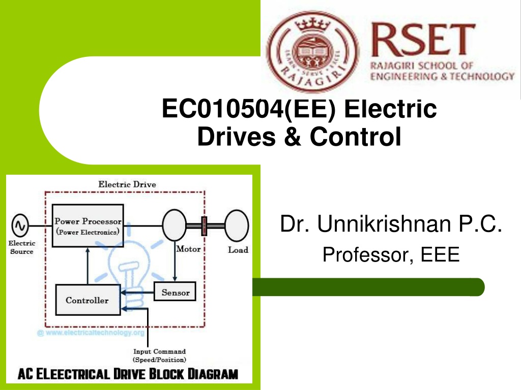
EC010504(EE) Electric Drives & Control Dr. Unnikrishnan P.C. Professor, EEE
Module II Transformer Three Phase Induction Motor Single Phase Induction Motor Alternator Synchronous Motor
Induction Motor Advantages Robust; No brushes. No contacts on rotor shaft High Power/Weight ratio compared to DC motor Lower Cost/Power Easy to manufacture Almost maintenance-free, except for bearing and other mechanical parts wide range of power ratings: fractional HP to 10 MW
Induction Motor Disadvantages Essentially a fixed-speed machine Speed is determined by the supply frequency To vary its speed need a variable frequency supply
Construction An induction motor has two main parts a stationary stator consisting of a steel frame that supports a hollow, cylindrical core core, constructed from stacked laminations (why?), having a number of evenly spaced slots, providing the space for the stator winding
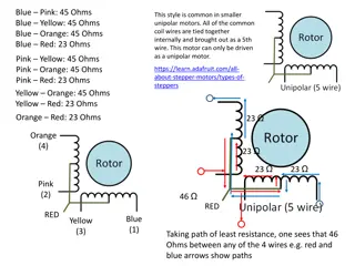
Construction-Rotor Two basic designs Squirrel-Cage: conducting copper or aluminium bars laid into slots and shorted at both ends by shorting rings. (Squirrel Cage Induction Motor) Wound-Rotor: complete set of three-phase windings exactly as the stator. Usually Y- connected, the ends of the three rotor wires are connected to 3 slip rings on the rotor shaft. In this way, the rotor circuit is accessible. (Slip-Ring Induction Motor)
Construction Squirrel cage rotor Wound rotor Notice the slip rings
Construction-Wound Rotor Slip Ring Induction Motor Slip rings Cutaway in a typical wound- rotor IM. Notice the brushes and the slip rings Brushes
Rotating Magnetic Field Balanced three phase windings, i.e. mechanically displaced 120 degrees form each other, fed by balanced three phase source A rotating magnetic field with constant magnitude is produced, rotating with a speed 120 = f e N s P Where fe is the supply frequency and P is the no. of poles and nsync is called the synchronous speed in rpm
Synchronous speed P 50 Hz 60 Hz 2 3000 3600 4 1500 1800 6 1000 1200 8 750 900 10 600 720 12 500 600
Principle of operation This rotating magnetic field cuts the rotor windings and produces an induced voltage in the rotor windings Due to the fact that the rotor windings are short circuited, for both squirrel cage and wound-rotor, a current flows in the rotor windings The rotor current produces another magnetic field A torque is produced as a result of the interaction of those two magnetic fields ????= ????? Where ????is the induced torque and BR and BS are the magnetic flux densities of the rotor and the stator respectively.
Induction Motor Speed At what speed will the IM run? Can the IM run at the synchronous speed, why? If rotor runs at the synchronous speed, which is the same speed of the rotating magnetic field, then the rotor will appear stationary to the rotating magnetic field and the rotating magnetic field will not cut the rotor. So, no induced current will flow in the rotor and no rotor magnetic flux will be produced so no torque is generated and the rotor speed will fall below the synchronous speed When the speed falls, the rotating magnetic field will cut the rotor windings and a torque is produced
Induction Motor Speed So, the IM will always run at a speed lower than the synchronous speed The difference between the motor speed and the synchronous speed is called the Slip S = ?? ?? ?? Where ??= speed of the magnetic field ??= mechanical shaft speed of the motor S = The slip
The Slip Notice that : if the rotor runs at synchronous speed s = 0 if the rotor is stationary s = 1 Slip may be expressed as a percentage by multiplying the above eq. by 100, notice that the slip is a ratio and doesn t have units
Frequency The frequency of the voltage induced in the rotor is given by P n f = r 120 Where fr= the rotor frequency (Hz) P = number of stator poles n = slip speed (rpm) = ( ) P n n s m f r 120 P sn = = s sf e 120
Torque While the input to the induction motor is electrical power, its output is mechanical power and for that we should know some terms and quantities related to mechanical power Any mechanical load applied to the motor shaft will introduce a Torque on the motor shaft. This torque is related to the motor output power and the rotor speed ???? ?? and ??= 2??? 60 rad/s ?????=
Horse Power Another unit used to measure mechanical power is the horse power It is used to refer to the mechanical output power of the motor Since we, as an electrical engineers, deal with watts as a unit to measure electrical power, there is a relation between horse power and watts. hp = 746 ?????
Torque-Slip Equation ? ? ?2?2??? 2 ??2 ?2 ? = ? ?2 2+ (??2)2 2+ (??2)2 ?2 ?2 2?2 ???2 2+ (??2)2 ? = ?2
Torque-Slip Characteristics ??? ???? ?+ (???)? ? = ?? Low Slip Region: ?? ? High Slip Region: ??1 ?
Starters- Squirrel Cage IM Direct-On-line Starting Stator Rheostat Starting Autotransformer Starting Star-Delta Starter
Direct On-Line(DOL) Starter Used for motors upto 2 kW Starting torque about twice the full load torque
Stator Rheostat Starter Advantages: High PF during start, Less Expensive, Smooth acceleration Disadvantages: Losses in Resistors, Expensive, Low torque efficiency
Auto-Transformer Starter Advantages: High torque/Ampere, Long starting period, Can be used for star and delta connected motors, Disadvantages: Low PF (Lagging), Higher cost
Star-Delta Starter Reduced starting current but the starting torque is also reduced by the same amount Limited to applications where high starting torque is not necessary
Starters- Slip Ring IM Rotor Rheostat Autotransformer Starting Star-Delta Starter
Rotor Rheostat Starter for Slip Ring IM By increasing rotor resistance, the rotor current is reduced at starting. The torque is increased due to improvement in PF Such motors can be started under load
Power losses in Induction Machines Copper losses Copper loss in the stator (PSCL) = I12R1 Copper loss in the rotor (PRCL) = I22R2 Core loss (Pcore) Mechanical power loss due to friction and windage How this power flow in the motor?
Power Relations = = 3 cos 3 cos P V I V I in L L ph ph = 2 3 SCL P I R ???? ?????? ?????? ???? 1 1 = + ( ) P P SCL P core P ??? ??? ??? ????? AG in = 2 2 3 RCL P I R ???? ????? ?????? ???? 2 = conv P P RCL P ,????? ? ? ?????????? ????? ????????? ?? ??? ?????? AG ????? ?? = + ( ) P conv P P stray P ?????= + out f w
Torque-speed characteristics Typical torque-speed characteristics of induction motor
Maximum torque Effect of rotor resistance on torque-speed characteristic
Speed Control Methods of IM Induction Motor Speed Control From Stator Side By Changing The Applied Voltage 2?2 2+ (??2)2 ,T ??2 By Changing The Applied Frequency Constant V/F Control Of Induction Motor- Most Popular Changing The Number Of Stator Poles ???2 2 ? = ?2 120 f = e N s P
Constant V/F Control Of Induction Motor If the supply frequency is reduced keeping the rated supply voltage, the air gap flux will tend to saturate causing excessive stator current and distortion of the stator flux wave. If the ratio of voltage to frequency is kept constant, the flux remains constant. Also, the developed torque remains approximately constant.
Speed Control Methods Of IM .. Induction Motor Speed Control From Rotor Side Rotor Rheostat Control Cascade Operation By Injecting EMF In Rotor Circuit: By changing the phase of injected emf, speed can be controlled
Example A 208-V, 10hp, four pole, 60 Hz, Y-connected induction motor has a full-load slip of 5 percent 1. What is the synchronous speed of this motor? 2. What is the rotor speed of this motor at rated load? 3. What is the rotor frequency of this motor at rated load? 4. What is the shaft torque of this motor at rated load?
Solution 120 f 120(60) 4 = = = 1800 1. e sync n rpm P = = (1 (1 0.05) 1800 1710 ) n s n 2. m s = rpm = = = 0.05 60 3 f sf Hz r e 3. P P = = out out n load 2 m m 4. 60 10 1710 2 746 / hp watt hp = = 41.7 . N m (1/60)
Example A 480-V, 60 Hz, 50-hp, three phase induction motor is drawing 60A at 0.85 PF lagging. The stator copper losses are 2 kW, and the rotor copper losses are 700 W. The friction and windage losses are 600 W, the core losses are 1800 W, and the stray losses are negligible. Find the following quantities: 1. The air-gap power PAG. 2. The power converted Pconv. 3. The output power Pout. 4. The efficiency of the motor.
Solution = 3 cos P V I in L L 1. = 3 480 60 0.85 = 42.4 kW = = P P SCL P core P AG in 42.4 2 1.8 = 38.6 kW = conv P P RCL P AG 700 1000 = = 38.6 37.9 kW 2. = P conv P F W P & out 600 1000 = = 37.9 37.3kW 3.
Solution 37.3 0.746 = = 50 hp P out P = 100% out P 4. in 37.3 42.4 = = 100 88%
Example A two-pole, 50-Hz induction motor supplies 15kW to a load at a speed of 2950 rpm. 1. What is the motor s slip? 2. What is the induced torque in the motor in N.m under these conditions? 3. What will be the operating speed of the motor if its torque is doubled? 4. How much power will be supplied by the motor when the torque is doubled?
Solution 120 120 50 2 3000 2950 3000 f = = = 3000 rpm sync n e P 1. sync n n m = = = 0.0167 or 1.67% s sync n no given P f W + = = 2. assume and conv P load P ind load 15 10 3 conv P = = = 48.6 N.m 2 60 ind 2950 m
Solution 3. In the low-slip region, the torque-speed curve is linear and the induced torque is direct proportional to slip. So, if the torque is doubled the new slip will be 3.33% and the motor speed will be = = (1 0.0333) 3000 = (1 ) 2900 rpm n s n m P sync = conv ind m 4. 2 60 = (2 48.6) (2900 = ) 29.5 kW
Question? Q: How to change the direction of rotation? A: Change the phase sequence of the power supply.
Question? Q: Why rotor core loss in a three phase induction motor negligible? A: Usually we operate motor at slip in the range 0.04 ~ 0.06, thus for a stator frequency of 50 Hz , rotor frequency is around 2~3 Hz. As core losses are proportional to square of frequency (Eddy current losses) or proportional to frequency ( Hysteresis losses) , therefore the value of the Core loss is negligible for rotor.
 Electric")


 Starter")