Overview of Multivibrators: Types and Applications
Multivibrators are electronic circuits used for various applications such as oscillators, timers, and flip-flops. They consist of two amplifying devices cross-coupled by resistors or capacitors. The three main types are astable, monostable, and bistable multivibrators, each serving different purposes in generating square waves or timed intervals. These circuits find applications in systems where precise timing is required, like frequency dividers. The operation and functionality of a monostable multivibrator are detailed, highlighting the trigger input and the timing network for pulse generation.
Download Presentation

Please find below an Image/Link to download the presentation.
The content on the website is provided AS IS for your information and personal use only. It may not be sold, licensed, or shared on other websites without obtaining consent from the author. Download presentation by click this link. If you encounter any issues during the download, it is possible that the publisher has removed the file from their server.
E N D
Presentation Transcript
Multivibrator is an electronic circuit used to implement a variety of simple two-state devices such as relaxation oscillators, timers and flip-flops. It consists of two amplifying devices (transistors, vacuum tubes or other devices) cross-coupled by resistors or capacitors. The first multivibrator circuit, the astable multivibrator oscillator, was invented by Henri Abraham and Eugene Bloch during World War I. They called their circuit a "multivibrator " because its output waveform was rich in harmonics.
The three types of multivibrator circuits are: Astable multivibrator, in which the circuit is not stable in either state it continually switches from one state to the other. It functions as a relaxation oscillator. Monostable multivibrator, in which one of the states is stable, but the other state is unstable (transient). A trigger pulse causes the circuit to enter the unstable state. After entering the unstable state, the circuit will return to the stable state after a set time. Such a circuit is useful for creating a timing period of fixed duration in response to some external event. This circuit is also known as a one shot. Bistable multivibrator, in which the circuit is stable in either state. It can be flipped from one state to the other by an external trigger pulse. This circuit is also known as a flip-flop. It can store one bit of information, and is widely used in digital logic and computer memory.
Multivibrators find applications in a variety of systems where square waves or timed intervals are required. For example, before the advent of low-cost integrated circuits, chains of multivibrators found use as frequency dividers. NOT Gate Monostable Multivibrator
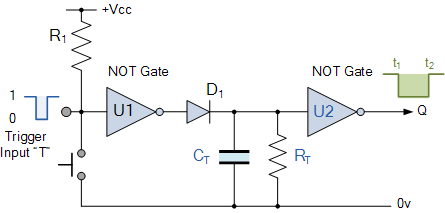
Initially the trigger input T is HIGH at a logic level 1 so that the output from the first NOT gate U1 is LOW at logic level 0 . The timing resistor, RTand the capacitor, CTare connected together in parallel to the input of the second NOT gate U2. As the input to U2 is LOW its output at Q will be HIGH. When a logic level 0 pulse is applied to the trigger input T of the first NOT gate it changes state and produces a logic level 1 output. The diode D1 passes this logic-1 voltage level to the RC timing network. The voltage across the capacitor, CTincreases rapidly to this new voltage level, which is also connected to the input of the second NOT gate. This in turn outputs a logic 0 at Q and the circuit stays in this Meta-stable state as long as the trigger input T applied to the circuit remains LOW. When the trigger signal returns HIGH again, the output from the first NOT gate goes LOW to logic 0 (NOT gate principals) and the fully charged capacitor starts to discharge itself back through the parallel resistor connected across it. When the voltage across the capacitor drops below the lower threshold value of the input to the second NOT gate, its output switches back again producing a logic level 1 at Q. The diode D1 prevents the timing capacitor from discharging itself back through the first NOT gates output.
Then, the Time Constant for a NOT gate Monostable Multivibrator is given as T = 0.8RC + Trigger in seconds. One main disadvantage of Monostable Multivibrators is that the time between the application of the next trigger pulse T has to be greater than the RC time constant of the circuit.
Astable Multivibrator Circuits Astable Multivibrators: are the most commonly used type of multivibrator circuit. An astable multivibrator is a free running oscillator that have no permanent meta or steady state but is continually changing its output from one state (LOW) to another state (HIGH) and then back again. This continual switching action from HIGH to LOW and LOW to HIGH produces a continuous and stable square wave output which switches abruptly between the two logic levels making it ideal for timing and clock pulse applications.
As with the previous monostable multivibrator circuit above, the timing cycle is determined by the RC time constant of the resistor-capacitor, RC Network. Then the output frequency can be varied by simply changing the value(s) of the resistors and capacitor in the circuit.
The astable multivibrator circuit uses two CMOS NOT gates .Suppose that initially the output from the NAND gate U2 is HIGH at logic level 1 , then the input must therefore be LOW at logic level 0 (NAND gate principles) as will be the output from the first NAND gate U1. Capacitor, C is connected between the output of the second NAND gate U2 and its input via the timing resistor, R2. The capacitor now charges up at a rate determined by the time constant of R2and C. As the capacitor, C charges up, the junction between the resistor R2and the capacitor, C, which is also connected to the input of the NAND gate U1 via the stabilising resistor, R2decreases until the lower threshold value of U1 is reached. At this point U1 changes state and the output of U1 now becomes HIGH. This change causes NAND gate U2 to also change state as its input has now changed from a logic 0 to a logic 1 condition resulting in the output of NAND gate U2 becoming LOW. Capacitor C is now becomes reverse biased so starts to discharge itself through the input of U1. Capacitor, C charges up again in the opposite direction determined by the time constant of both R2and C as before until it reaches the upper threshold value of NAND gate U1. This causes U1 to change state and the cycle repeats itself over again.
Then, the time constant for a NAND gate Astable Multivibrator is given as T = 2.2RC in seconds with the output frequency given as = 1/T. For example: if the resistor R2= 10k and the capacitor C = 45nF, the oscillation frequency of the circuit would be given as: Then the output frequency is calculated as being 1kHz, which equates to a time constant of 1ms. Thus the output waveform would look something like this:


