Understanding Runway Length Requirements and Components in Aviation Design

Explore the essential aspects of runway length requirements, pavement components, and critical distances in aviation design, including normal take-off conditions, engine failure scenarios, and landing considerations. Gain insights into governmental regulations, aircraft operations, and safety factors influencing runway design.

Download Presentation

Please find below an Image/Link to download the presentation.
The content on the website is provided AS IS for your information and personal use only. It may not be sold, licensed, or shared on other websites without obtaining consent from the author. Download presentation by click this link. If you encounter any issues during the download, it is possible that the publisher has removed the file from their server.
E N D
Presentation Transcript
Runway Length Requirements Governmental regulations Airport location Critical aircraft Source: AC 150/5325-4B - Runway Length Requirements for Airport Design Source: AC 150/5325-4B - Runway Length Source: AC 150/5325-4B - Runway Length Requirements for Airport Design Requirements for Airport Design
Runway Pavement Components Full strength (FS) Take-off & Landing Partial strength (PS) Take-off Clear Way (CL) Take-off
Length Conditions Normal take-off Engine failure Continue take-off Abort take-off Landing
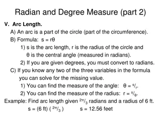
Some Terms (see fig 3-22) Lift off distance (LOD) Threshold to wheels off the ground D35 Threshold to aircraft 35 feet above ground Take off distance (TOD) Runway length provided to D35with factor of safety applied = 1.15 D35(for normal takeoff) Take off roll or run (TOR) Full strength pavement; runway Accelerate and stop distance (DAS) Landing distance (LD)
Relationship of Distances 35 LOD D35 TOD
Normal Take-Off 35 LODN D35,N TODN = 1.15 D35,N Clear Zone (CLN,max) = 0.5(TODN -1.15 LODN) TORN = TODN CLN = FSN CLN FSN TODN
Engine Failure, Continue Engine fails 35 LODE D35,E TODE = D35,E (do not apply factor of safety) CLE,max = 0.5(TODE - LODE) TORE = TODE CLE = FSE CLE FSE TODE
Engine Failure, Abort Engine fails at V=V1 Stop DAS V1 = speed above which you continue to take off V2 = rotation or lift off speed TODA = DAS PSA FSA TODA
Landing Stop 50 SD FS = Runway LD LD = SD/0.6 LD = FSL FSL
Runway Layout PS (partial strength) = SW (stopway) CL PS CL PS FS = Runway FL Field Length (FL) = max {TODN,TODE, DAS, LD} FS = max {FSN,FSE, FSL} PS = DAS FS PSmin = 0 ft CL = min {FL-DAS, CLN,CLE} 1000 ft CLmin = 0 ft CL max=
Example (1/3) Distances for typical aircraft are as follows: LOD: Normal 6,000 ft; Failure 7,000 ft D35: Normal 7,000 ft; Failure 8,200 ft DAS: 7,900 ft and SD: 4,500 ft. (LD = 4500/.6=7500) Design the runway for bi-directional operations
Example (2/3) Normal take-off Engine failure, abort DAS = 7,900 ft TODN = 1.15(7000)= 8,050 ft CLN,max = 0.5(8050 -1.15(6000)) = 575 ft FSN = 8050-575 = 7,475 ft Engine failure, continue Landing TODE = 8,200 ft LD = 4500/0.60 =7,500 ft CLE,max = 0.5(8200 - 7000) =600 ft FSL = 7,500 ft FSE = 8200- 600 = 7,600 ft
Example (3/3) FL = max {8050, 8200, 7900, 7500} = 8,200 ft FS = max {7475, 7600, 7500} = 7,600 ft PS = 7900-7600 = 300 ft CL = min {8200-7900, 575, 600} = 300 ft 300 300 300 300 7600 8800 8200
Airport Location Adjustments Elevation 7% per 1,000 ft Fe= 0.07 E + 1; E in 000 s Temperature Ft =0.01[T (15-1.981E)]+1 Grade Fg = 0.1 G +1 Reference length (LR) LR from before LR = Actual length/(Fe Ft Fg) Or, Actual length = LR*(Fe Ft Fg)
Critical Aircraft Requirements Runway length affects Take-off weight Landing weight Runway lengths Take off Landing
Aircraft Weights Operating Empty Weight (OEW) No fuel or payload Maximum Takeoff Operating Weight (MTOW) Maximum Landing Weight (MALW) Maximum Structural Payload Weight (MSPW) Maximum Zero Fuel Weight OEW+MSPW Fuel Weight (FW)
Range at Max structural payload Payload and range with max fuel Max range with no payload (ferry range)
Payload Range Plots Max payload and reduced range if landing load is restricted (max structural landing weight) Max range and reduced payload if landing load is restricted (max structural landing weight)
Example (similar to ex 3-3) (1/8) A runway is planned for an airport at elevation 2,300 ft AMSL and average temperature of 92oF. The critical aircraft is a Boeing 737-200. Determine: 1. Runway length without weight limits 2. Weight limits for an 8,000 ft runway
Runway length without weight limits (2/8) Source: AC 150/5325-4A
Example (3/8) 100.4
Example (4/8) 69.5
Example (5/8) 69.5 100.4 Runway 8,545 ft w/0% grade MTOW 100,400 lbs
Example (6/8) Runway 5,650 ft w/0% grade, MLW 103,000 lbs
Example with 8000 foot R/W (7/8) 69.5 MTOW 97,160 lbs Runway 8,000 ft
Example (8/8) Distance to fly from this airport? MTOW 97,160 lbs OEW 67,238 lbs Pax+Fuel 29, 832 lbs 225 lbs/pax Fuel 15 lbs/mi 50 pax @ 1240 miles 60 pax @ 1090miles 75 pax @ 860 miles


")


 (1/8)")