Understanding I/O Systems and Devices
I/O systems and devices play a crucial role in computer operations. They can be categorized into block devices and character devices based on their functionalities. Block devices store information in fixed-size blocks with addresses, while character devices handle character streams. Some devices, like clocks and memory-mapped screens, don't fit neatly into these categories. The interaction between I/O devices and processors can be managed through polling or interrupt-driven methods. Additionally, Direct Memory Access (DMA) allows for more efficient data transfers between I/O devices and memory by bypassing the CPU. Special instruction I/O and memory-mapped I/O are also important concepts in managing I/O operations effectively.

Download Presentation

Please find below an Image/Link to download the presentation.
The content on the website is provided AS IS for your information and personal use only. It may not be sold, licensed, or shared on other websites without obtaining consent from the author. Download presentation by click this link. If you encounter any issues during the download, it is possible that the publisher has removed the file from their server.
E N D
Presentation Transcript
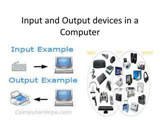
I/O Devices I/O devices can be roughly divided into two categories : block devices and character devices. Block Devices It stores information in fixed-size blocks, each one with its own address. Common block sizes range from 512 to 65,536 bytes. Examples are hard disks, Blu-ray discs, and USB sticks. Character Device It delivers or accepts a stream of characters, without regard to any block structure. Not addressable and does not have any seek operation. Examples are printers, network interfaces, mice, and most other devices that are not disk- like can be seen as character devices. Doesn't Really Fit Some devices don't fit into this division: For instance, clocks aren't block addressable, nor do they accept character streams. All they do is cause interrupts... at timed intervals. Memory-mapped screens do not fit this division either.
I/O Hardware 1. Polling I/O Polling is the simplest way for an I/O device to communicate with the processor. The process of periodically checking status of the device to see if it is time for the next I/O operation, is called polling. The I/O device simply puts the information in a Status register, and the processor must come and get the information. Most of the time, devices will not require attention and when one does it will have to wait until it is next interrogated by the polling program. This is an inefficient method and much of the processors time is wasted on unnecessary polls. Compare this method to a teacher continually asking every student in a class, one after another, if they need help. Obviously the more efficient method would be for a student to inform the teacher whenever they require assistance. 2. Interrupts I/O An alternative scheme for dealing with I/O is the interrupt-driven method. An interrupt is a signal to the microprocessor from a device that requires attention. A device controller puts an interrupt signal on the bus when it needs CPU s attention when CPU receives an interrupt, It saves its current state and invokes the appropriate interrupt handler using the interrupt vector (addresses of OS routines to handle various events). When the interrupting device has been dealt with, the CPU continues with its original task as if it had never been interrupted.
3. Direct Memory Access To reduce the overhead of interrupts, DMA hardware bypasses CPU to transfer data directly between I/O device and memory. DMA module itself controls exchange of data between main memory and the I/O device. CPU is only involved at the beginning and end of the transfer and interrupted only after entire block has been transferred, rather than a byte at a time. Direct Memory Access Controller :- DMA controller (DMAC) manages the data transfers and arbitrates access to the system bus. It contains several registers that can be written and read by the CPU. These include a memory address register, a byte count register, and one or more control registers.
1. Special Instruction I/O 2. Memory-mapped I/O 3. Direct memory access (DMA) 1. Special Instruction I/O This uses CPU instructions that are specifically made for controlling I/O devices. These instructions typically allow data to be sent to an I/O device or read from an I/O device. 2. Memory-mapped I/O When using memory-mapped I/O, the same address space is shared by memory and I/O devices. The device is connected directly to certain main memory locations so that I/O device can transfer block of data to/from memory without going through CPU. While using memory mapped IO, OS allocates buffer in memory and informs I/O device to use that buffer to send data to the CPU. I/O device operates asynchronously with CPU, interrupts CPU when finished. The advantage to this method is that every instruction which can access memory can be used to manipulate an I/O device. Memory mapped IO is used for most high-speed I/O devices like disks, communication interfaces.
Application I/O Interface 1. Block and Character Devices The block-device interface captures all the aspects necessary for accessing disk drives and other block-oriented devices. The device is expected to understand commands such as read () and wr it e (); if it is a random-access device, it is also expected to have a seek() command to specify which block to transfer next. Applications normally access such a device through a file-system interface. We can see that readO, write (), and seekO capture the essential behaviors of block-storage devices, so that applications are insulated from the low-level differences among those devices. 2. Network Devices Because the performance and addressing characteristics of network I/O differ significantly from, those of disk I/O, most operating systems provide a network I/O interface that is different from the read 0 -writ e () -seekO interface used for disks. One interface available in many operating systems, including UNIX and Windows NT, is the network socket interface. Think of a wall socket for electricity: Any electrical appliance can be plugged in. By analogy, the system calls in the socket interface enable an application to create a socket, to connect a local socket to a remote address (which plugs this application into a socket created by another application), to 13.3 Application I/O Interface 509 listen for any remote application to plug into the local socket, and to send and receive packets over the connection.
3. Blocking and Nonblocking IO Another aspect of the system-call interface relates to the choice between blocking I/O and nonblocking I/O. When an application issues a blocking system call, the execution of the application is suspended. The application is moved from the operating system's run queue to a wait queue. After the system call completes, the application is moved back to the run queue, where it is eligible to resume execution, at which time it will receive the values returned by the system call. The physical actions performed by I/O devices are generally asynchronous they take a varying or unpredictable amount of time. Nevertheless, most operating systems use blocking system calls for the application interface, because blocking application code is easier to understand than nonblocking application code. Some user-level processes need nonblocking I/O.
Secondary Storage Structure Secondary storage devices are those devices whose memory is non volatile, meaning, the stored data will be intact even if the system is turned off. Here are a few things worth noting about secondary storage. Secondary storage is also called auxiliary storage. Secondary storage is less expensive when compared to primary memory like RAMs. The speed of the secondary storage is also lesser than that of primary storage. Hence, the data which is less frequently accessed is kept in the secondary storage. A few examples are magnetic disks, magnetic tapes, removable thumb drives etc. Magnetic Disk Structure (Disk Fundamental) In modern computers, most of the secondary storage is in the form of magnetic disks. Hence, knowing the structure of a magnetic disk is necessary to understand how the data in the disk is accessed by the computer. A magnetic disk contains several platters. Each platter is divided into circular shaped tracks. The length of the tracks near the centre is less than the length of the tracks farther from the centre. Each track is further divided into sectors, as shown in the figure. Tracks of the same distance from centre form a cylinder. A read-write head is used to read data from a sector of the magnetic disk.
Disk Scheduling Algorithms but before discussing them lets have a quick look at some of the important terms: Seek Time : Seek time is the time taken to locate the disk arm to a specified track where the data is to be read or write. So the disk scheduling algorithm that gives minimum average seek time is better. Rotational Latency: Rotational Latency is the time taken by the desired sector of disk to rotate into a position so that it can access the read/write heads. So the disk scheduling algorithm that gives minimum rotational latency is better. Transfer Time: Transfer time is the time to transfer the data. It depends on the rotating speed of the disk and number of bytes to be transferred. Disk Access Time: Disk Access Time is: Disk Access Time = Seek Time + Rotational Latency + Transfer Time Disk Response Time: Response Time is the average of time spent by a request waiting to perform its I/O operation. Average Response time is the response time of the all requests. Variance Response Time is measure of how individual request are serviced with respect to average response time. So the disk scheduling algorithm that gives minimum variance response time is better.
Disk Scheduling Algorithms Disk scheduling is is done by operating systems to schedule I/O requests arriving for disk. Disk scheduling is also known as I/O scheduling. Disk scheduling is important because: Multiple I/O requests may arrive by different processes and only one I/O request can be served at a time by disk controller. Thus other I/O requests need to wait in waiting queue and need to be scheduled. Two or more request may be far from each other so can result in greater disk arm movement. Hard drives are one of the slowest parts of computer system and thus need to be accessed in an efficient manner. 1. FCFS Algorithms 2. SSTF Algorithms 3. SCAN Algorithms 4. CSCAN 5. LOOK 6. CLOOK
1. FCFS Algorithms FCFS is the simplest of all the Disk Scheduling Algorithms. In FCFS, the requests are addressed in the order they arrive in the disk queue. Advantages: Every request gets a fair chance No indefinite postponement Disadvantages: Does not try to optimize seek time May not provide the best possible service Let's take an example where the queue has the following requests with cylinder numbers as follows: 98, 183, 37, 122, 14, 124, 65, 67 Assume the head is initially at cylinder 56. The head moves in the given order in the queue i.e., 56 98 183 ... 67.
2. SSTF Algorithms In SSTF (Shortest Seek Time First), requests having shortest seek time are executed first. So, the seek time of every request is calculated in advance in queue and then they are scheduled according to their calculated seek time. As a result, the request near the disk arm will get executed first. SSTF is certainly an improvement over FCFS as it decreases the average response time and increases the throughput of system. Advantages: Average Response Time decreases Throughput increases Disadvantages: Overhead to calculate seek time in advance Can cause Starvation for request if it has higher seek time as compared to incoming requests High variance of response time as SSTF favors' only some requests Consider the previous example where disk queue looks like, 98, 183, 37, 122, 14, 124, 65, 67 Assume the head is initially at cylinder 56. The next closest cylinder to 56 is 65, and then the next nearest one is 67, then 37, 14, so on.
3. SCAN Algorithms In SCAN algorithm the disk arm moves into a particular direction and services the requests coming in its path and after reaching the end of disk, it reverses its direction and again services the request arriving in its path. So, this algorithm works like an elevator and hence also known as elevator algorithm. As a result, the requests at the midrange are serviced more and those arriving behind the disk arm will have to wait. This algorithm is also called the elevator algorithm because of it's behavior. Here, first the head moves in a direction (say backward) and covers all the requests in the path. Then it moves in the opposite direction and covers the remaining requests in the path. This behavior is similar to that of an elevator. Advantages: High throughput Low variance of response time Average response time Disadvantages: Long waiting time for requests for locations just visited by disk arm Let's take the previous example, 98, 183, 37, 122, 14, 124, 65, 67 Assume the head is initially at cylinder 56. The head moves in backward direction and accesses 37and 14. Then it goes in the opposite direction and accesses the cylinders as they come in the path.
4. CSCAN: In SCAN algorithm, the disk arm again scans the path that has been scanned, after reversing its direction. So, it may be possible that too many requests are waiting at the other end or there may be zero or few requests pending at the scanned area. These situations are avoided in CSAN algorithm in which the disk arm instead of reversing its direction goes to the other end of the disk and starts servicing the requests from there. So, the disk arm moves in a circular fashion and this algorithm is also similar to SCAN algorithm and hence it is known as C-SCAN (Circular SCAN). Advantages: Provides more uniform wait time compared to SCAN 5. LOOK: It is similar to the SCAN disk scheduling algorithm except the difference that the disk arm in spite of going to the end of the disk goes only to the last request to be serviced in front of the head and then reverses its direction from there only. Thus it prevents the extra delay which occurred due to unnecessary traversal to the end of the disk. 6. CLOOK: As LOOK is similar to SCAN algorithm, in similar way, CLOOK is similar to CSCAN disk scheduling algorithm. In CLOOK, the disk arm inspite of going to the end goes only to the last request to be serviced in front of the head and then from there goes to the other end s last request. Thus, it also prevents the extra delay which occurred due to unnecessary traversal to the end of the disk.
Disk Management Low-level formatting, or physical formatting Dividing a disk into sectors that the disk controller can read and write. z To use a disk to hold files, the operating system still needs to record its own data structures on the disk z Partition the disk into one or more groups of cylinders z Logical formatting or making a file system z Boot block initializes system z The bootstrap is stored in ROM z Bootstrap loader program z Methods such as sector sparing used to handle bad blocks
https://www.cs.uic.edu/~jbell/CourseNotes/OperatingSystems/13_IOSystems.htmlhttps://www.cs.uic.edu/~jbell/CourseNotes/OperatingSystems/13_IOSystems.html