Cryostat Engineering for SC Devices Training at CERN - November 2022
Explore the technical training on Cryostat Engineering for Superconducting devices at CERN in November 2022. Dive into the design aspects, static heat loads, and mass flows for a 400 MHz cryomodule. Tasks include conceptual design of cryostats, calculating thermal parameters, supporting systems, and assembly methods. Detailed tables provide insights into heat loads and mass flows at varying temperatures.

Download Presentation

Please find below an Image/Link to download the presentation.
The content on the website is provided AS IS for your information and personal use only. It may not be sold, licensed, or shared on other websites without obtaining consent from the author. Download presentation by click this link. If you encounter any issues during the download, it is possible that the publisher has removed the file from their server.
E N D
Presentation Transcript
Tutorial Technical Training: Cryostat Engineering for SC devices CERN, 7-9 November 2022
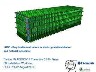
FCCee, RF cryogenic layout, 400 MHz Cryomodule 1 of 35 cryomodules per side
400 MHz cavities, 2-cell He vapor collector 50 4.2 K saturated liquid helium, 1.0 bar ~10m vapor out Liquid in RF Coupler 50 200 x 2 Interconnections 400 Cavity: copper, 3-mm thick Cavity mass: 150 kg Helium vessel: thickness TBD, st.steel (304L grade) Helium vessel mass: (304L): 200 kg Beam tube cone (304L) RF coupler tube (304L) Approximate mass of cavity/helium tank/RF coupler assembly: 500 kg Cavity 300 tube length: 500 Inlet 100 500 730 Beam tube cone, thickness: 1 mm He tank 800 Cavity 740 He tank volume ~0.28m3
Task 1. Cryostat design 1. Conceptual design of a cryostats for the 400 MHz cryomodule containing 4 cavities. Make a schematic design (simplified sketch, use ppt or any other S/W tool), and make a preliminary engineering design as follows: a. Calculate helium tank thickness, for a maximum allowable pressure of 4 bar b. Calculate vacuum vessel: material, diameter and thickness c. Calculate thermal shielding: material, diameter, thickness. Propose a possible supporting principle. d. Design of the supporting system. Choose type (column, tie rods, etc.), make a conceptual design (materials and sizing for mechanical and thermal requirements). Consider maximum loads from road transport: vertical: 7 m/s2; lateral: 4 m/s2; longitudinal: 6 m/s2 and a minimum Safety Factor on 2 on 0.2. e. Propose a possible assembly method of the cavities string inside the vacuum vessel 2. Calculate the static thermal performance (Heat Loads) and total cooling mass flow needs, for the following : a. Supporting system (no heat intercept) b. RF couplers (with active vapor cooling or not) c. Beam tubes cold to warm transitions (cones between 300 K and 4.2 K, no heat intercept). (neglect conduction path of bellows) d. Thermal radiation from vacuum vessel and thermal shielding (flat plate approximation). Calculate the radiation load in the absence of a thermal shield. e. Calculate liquid boil-off mass flows, liquefaction load for ideal vapor cooling of couplers, and thermal shield mass flow assuming Tin=50 K and Tout= 55 K.
Task 1.1. Table of design parameters Item 1 a. 1 b. 1 c. 1 d. 1 e. Description Value Comments
Task 1.2. Table of Static Heat Loads and mass flows Source of HL HL (W) @ 4.2 K HL (W) @ 50 K 4.2 K liquid boil- off (g/s) Liquefaction load (g/s) Thermal shield mass flow (g/s) (with Tin=50K, Tout=55 K ) Supports conduction - - - Beam tube cones conduction - - - RF Couplers conduction (uncooled) - - - - RF Couplers conduction (ideal vapor cooling) - Radiation, with thermal shield @ 50 K - Radiation, without thermal shield - - - Radiation from beam tube cones Totals - - -
Task 2. Cool-Down The cool down from 293 K is obtained by boil-off of liquid helium at 4.2 K (1 bar) entered from the bottom of the helium vessels. a. Calculate the liquid helium need (mass in kg) for cooling down to 4.2 K helium the mass of cavity+helium tank. Consider, during the CD process, an average effectiveness in the use of the sensible heat of helium vapor between 4.2 K and 100 K (exhaust temperature at the exit of the cavity). How correct is this assumption? (Neglect, in the calculation, the contribution from static heat loads to the power balance). b. Calculate the average cooling power for a cool down from 293 K to 100 K in 12 h, assuming that cavity/helium vessel are isothermal in the cooling process
Task 2 Results Item a. b. Value Comments
Task 3. RF operation, helium boil-off and pumping During RF operation of a cryomodule, a dynamic heat load 175 W is added to the static heat load calculated previously. Vapours are pumped back to the refrigerator through a 1 000 m long, DN200 smooth pipe, routed in a shielded and vacuum insulated transfer line. a. Calculate the total boil-off rate in saturated helium at 4.2 K and 1 bar (g/s) for one cryomodule b. Calculate the pumping pressure drop along the line, neglecting static heat loads along the line c. Calculate the total pressure drop for 35 cryomodules all operating with the same dynamic load d. If the cavities operate at 2K, 30 mbar, calculate the pressure drop along the line
Task 3 Results Item a. b. c. d. Value Comments