Understanding Reservoir Inflows and Computing Methods
Explore the methods for computing reservoir inflows, including mass balance formulas, known and unknown variables, and techniques to handle negative values. Learn about linking to HMS for hydrologic engineering, estimating local inflows, and utilizing smoothing techniques for accurate results.
Download Presentation

Please find below an Image/Link to download the presentation.
The content on the website is provided AS IS for your information and personal use only. It may not be sold, licensed, or shared on other websites without obtaining consent from the author. Download presentation by click this link. If you encounter any issues during the download, it is possible that the publisher has removed the file from their server.
E N D
Presentation Transcript
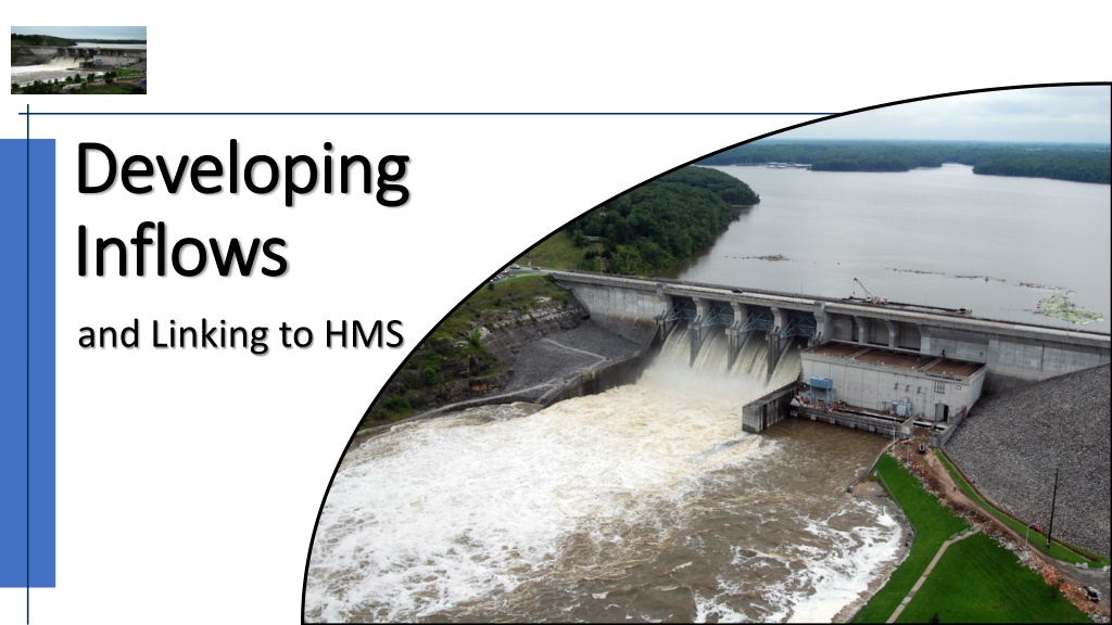
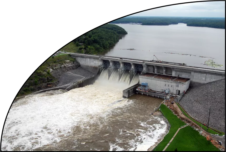
Developing Developing Inflows Inflows and Linking to HMS Hydrologic Engineering Center
Overview Overview Reservoir Inflows Reservoir Inflows Methods for Computing Local Inflows Methods for Computing Local Inflows Sources of Local Inflows Sources of Local Inflows Linking to HMS results Linking to HMS results
Methods for Computing Reservoir Inflows Methods for Computing Reservoir Inflows Mass Balance Formula Mass Balance Formula ??+? ?? ? =??+?+ ?? ??+?+ ?? ?????? ? ? Elev Elev- -Stor Stor Curve (2020) Curve (2020) Known Variables Final Storage (St+1) Initial Storage (St) Final Outflow (Ot+1) Initial Outflow (Ot) Losses 1990 1990 1970 1970
Methods for Computing Reservoir Inflows Methods for Computing Reservoir Inflows Mass Balance Formula Mass Balance Formula ??+? ?? ? =??+?+ ?? ??+?+ ?? ?????? ? ? Known Variables Final Storage (St+1) Initial Storage (St) Final Outflow (Ot+1) Initial Outflow (Ot) Losses Losses: Reservoir Evaporation Seepage Gate Leakage could be in the outflow already Water Supply/Irrigation
Methods for Computing Reservoir Inflows Methods for Computing Reservoir Inflows Mass Balance Formula Mass Balance Formula x x x x ??+? ?? ? =??+?+ ?? ??+?+ ?? ?????? ? ? Unknown Variables Final Inflow (It+1) Initial Inflow (It) x x Known Variables Final Storage (St+1) Initial Storage (St) Final Outflow (Ot+1) Initial Outflow (Ot) Losses x x ??+?+ ?? ? = ??????? ??????
Methods for Computing Reservoir Inflows Methods for Computing Reservoir Inflows Mass Balance Formula Mass Balance Formula ????=??+? ?? +??+?+ ?? + ?????? ? ? Utilize smoothing techniques to reduce or eliminate negative values while maintaining volume
Methods for Computing Local Inflows Methods for Computing Local Inflows 1. Derive the locals from Observed flows By hand Use a spreadsheet or script Use a program like HMS or ResSim 2. Use a calibrated hydrology (HMS) model to estimate the local inflows
Deriving Locals from Observed Deriving Locals from Observed Local Flow = Total flow Local Flow = Total flow - - Routed flow Gather observed (total) flows at gages. US Gage, DS Gage US Gage, DS Gage Route observed from gage to gage US Gage to DS Gage US Gage to DS Gage Subtract. DS Gage FLOW DS Gage FLOW- -LOCAL = LOCAL = DS Gage FLOW DS Gage FLOW US Gage to DS Gage FLOW US Gage to DS Gage FLOW Adjust for losses evaporation, seepage, withdrawals Utilize smoothing techniques to reduce or eliminate negative values while maintaining volume Routed flow
To perform the routing To perform the routing Use paper and pencil Use Use DSSVue DSSVue math functions math functions Script it Write an Excel Macro Use HMS Use HMS Use ResSim Use ResSim
Using HEC Using HEC- -HMS HMS to to estimate estimate local inflow local inflow Rainfall/Snowmelt Runoff Model Rainfall/Snowmelt Runoff Model Turn ON the Local Flow option in the Basin Model. HMS will: perform subbasin runoff computations route and combine those flows through the basin compute local flow at all junctions model Local Flow = Total Flow Flow routed in = sum of the subbasin flows junctions in the
Using HEC Using HEC- -HMS HMS - - to to derive derive local inflow local inflow Runoff Model Runoff Model or or Routing Model Attach an observed flow to each junction Turn ON the Local Flow option in the Basin Model. Specify Blending Blending at each gage HMS will replace simulated flows with Observed Flows at each gage route flows through the model compute local flow at all junctions in the model Local Flow = Total (Observed) Flow Flow routed in Routing Model junction representing a gage
Using ResSims OSI Using ResSim s OSI - - to to derive derive local inflows local inflows In the network In the network Identify a local inflow at each headwater junction. Identify a local inflow at each junction representing a gage. Turn On observed total flow at each junction receiving inflow Turn On observed total flow at each reservoir outflow junction In the alternative In the alternative Create a unique dummy time-series record for each interior inflow junction Mapeach dummy time-series to its associated local inflow Map an observed observed time series to each headwater local inflow Map Map an observed observed time series to the observed observed total flow of each interior junction (gage location) at each reservoir outflow junction local inflow local inflow
Use ResSims OSI, continued. Use ResSim s OSI, continued. In the OSI In the OSI - - Define a local inflow OSI Variable at each (interior) gage location Compute Locals Compute Locals click on the OSI Action button Compute Locals ResSim will: Replace (in memory) the computed total flow at each junction with the observed flow (where it has it), Route those flows through the network to each local inflow OSI Variable location Subtract the routed flow from the observed total flow to get the computed local Overwrite the dummy time series mapped to the local inflow with the computed local inflow time series (in the simulation.dss file). Perform a standard compute, using the newly computed locals Compute Locals
Use ResSims OSI, continued. Use ResSim s OSI, continued.
(Other) Sources of Local Inflows (Other) Sources of Local Inflows Existing Study Models Existing Study Models Rainfall & Snowmelt Runoff Models e.g., HEC-HMS Partner Agencies Partner Agencies e.g., NOAA e.g., NOAA- -NWS Derived from Observed Data Derived from Observed Data- - CWMS and/or Study Databases Automated Computations Specific Study Effort NWS CWMS and/or Study Databases
Linking HMS to ResSim Linking HMS to ResSim (A simple Example) (A simple Example) A Simple ResSim Model: A Simple ResSim Model:
An HMS Model An HMS Model for the same simple watershed for the same simple watershed
Linking HMS to ResSim Linking HMS to ResSim At ResSim headwater Identify a local inflow Identify a local inflow to represent the total inflow entering at this junction Give it a name Give it a name similar to the HMS element name producing the time series and an indicator of what kind of flow is needed in this case, FLOW or TOTAL FLOW In the alternative, map to the associated HMS element s total flow total flow (c-part = FLOW) to this headwater inflow headwater junctions,
Linking HMS to ResSim Linking HMS to ResSim At ResSim interior Identify a local inflow Identify a local inflow to represent the incremental local flow entering at this junction Give it a name Give it a name similar to the HMS element name producing the time series and an indicator of what kind of flow is needed in this case, LOCAL or FLOW-LOCAL In the alternative, map the associated HMS element s local flow local flow (c-part = FLOW-LOCAL) to this local inflow interior junctions
Linking HMS to ResSim Linking HMS to ResSim At ResSim interior a connected tributary but ResSim does not a connected tributary but ResSim does not Identify Identify another another local inflow local inflow at this junction to represent the tributary inflow Give it a name Give it a name similar to the HMS element name producing the time series and an indicator of what kind of flow is needed in this case, it will usually be FLOW. NOTE: this element is most often a reach, but it could be almost any HMS element type whose computed outflow represents the total tributary flow In the alternative, map the associated HMS element s FLOW to this local inflow interior junctions where HMS has where HMS has
Linking HMS to ResSim Linking HMS to ResSim At ResSim Reservoir Inflow Reservoir Inflow junctions In general, follow instructions on previous slide However However, the modeling of reservoir inflows in the two models can vary significantly. Conditions that may make it difficult to identify the appropriate inflow(s) for the ResSim reservoir: In HMS, all inflowing elements link directly to a reservoir element In HMS, all inflowing elements link to a sink element In HMS, all inflowing elements link to a single reservoir inflow junction, BUT in ResSim, the associated reservoir has two or more inflow junctions Consider changing the HMS model most changes are trivial Consider changing the ResSim model - usually not quite as easy as HMS
Take Take- -Home Points Home Points ResSim needs ResSim needs Total flow for headwater junctions (i.e. reservoirs or tributary headwater) Total flow for headwater junctions (i.e. reservoirs or tributary headwater) Incremental local flows for Incremental local flows for interbasin interbasin junctions, not total flows Observed / Gaged data reflect total flows Observed / Gaged data reflect total flows Incremental locals must be calculated Incremental locals must be calculated Modeled with a Rainfall-Runoff (HMS) model Derived from Observed By hand, scripts, DSSVue, Using HMS Using ResSim junctions, not total flows
