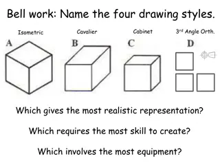
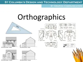
Introduction to Engineering Drawing Language and Drawing Tools
Engineering Drawing Language uses lines to depict object surfaces, edges, and contours, while Freehand Drawing is sketched without instruments. Drawing Instruments ensure precise drawings to scale. Learn to draw horizontal and vertical lines, and angles using drawing tools like T-Square and triangles.

Download Presentation

Please find below an Image/Link to download the presentation.
The content on the website is provided AS IS for your information and personal use only. It may not be sold, licensed, or shared on other websites without obtaining consent from the author. Download presentation by click this link. If you encounter any issues during the download, it is possible that the publisher has removed the file from their server.
E N D
Presentation Transcript
Engineering Drawing Language communicates an idea or design use Lines to represent the surfaces, edges and contours of objects. Surface Edge
Freehand Drawing The lines are sketched without using instruments other than pencils and erasers. Example
Drawing Instruments Instruments are used to draw straight lines, circles, and curves concisely and accurately. Thus, the drawings are usually made to scale. Example
Drawing Tools Drawing Tools T-Square Triangles Straight line
Draw a Horizontal Line 1. Press the T-square head against the left edge of the table. 2. Smooth the blade to the right.
Draw a Horizontal Line 3. Lean the pencil at an angle about 60owith the paper in the direction of the line. 4. Draw the line from left to right while rotating the pencil slowly .
Draw a Vertical Line 1. Set T-square as before. Place any triangle on T-square edge. 2. Slide your left hand to hold both T-square and triangle in position.
Draw a Vertical Line 3. Lean the pencil to the triangle. 4. Draw the line upward while rotating the pencil slowly.
Draw a Line at 45owith Horizontal 1. Place 45otriangle on the T-square edge and press them firmly against the paper. 2. Draw the line in the direction as shown below.
Draw a line at Angle 30o and 60o 1. Place 30o-60otriangle on the T-square edge and press them firmly against the paper. 2. Draw the line in the direction as shown below.
Draw the lines at 15o increments 0 deg. 15 deg. = 30 + 45 deg 30 deg. Already 45 deg. demonstrated. 60 deg. 75 deg. = 30 + 45 deg 90 deg. Already demonstrated.
Draw the Line Passing Through Two Given Points 1. Place the pencil tip at one of the points. 2. Place the triangle against the pencil tip. 3. Swing the triangle around the pencil tip until its edge align with the second point. 4. Draw a line. A Given B A B
Drawing Tools Drawing Tools Preparing the Compass 1. Sharpen the lead with a sandpaper. 2. Adjust the needle and the lead so that the tip of the needle extends slightly more than the lead. Compasses Arc, Circle needle lead
Using the Compass 1. Locate the center of the circle by two intersecting lines. 2. Adjust the distance between needle and lead to a distance equal to radius of the circle. 3. Set the needle point at center.
Using the Compass 4. Start circle. Apply enough pressure to the needle, holding compass handle between thumb and index fingers. 5. Complete circle. Revolve handle clockwise. Don't Use Circle Template
Drawing Tools Drawing Tools HB for thick line ( HB for thick line (0.7 0.7 mm or mm or 0.5 0.5 mm) mm) 2 2H for H for thin line thin line & & 3 3H or H or 4 4H for guiding lines H for guiding lines Adhesive Tape Pencils
Drawing Tools Drawing Tools French Curves Pencil Eraser Erasing Shield
Drawing Tools Drawing Tools PROTRACTOR Scale (ruler)
Drawing Tools Drawing Tools Note :Don t use any template of: - Circles. - Ellipses. - Letters.
Drawing Sheets (Papers) Trimmed paper of a size A0 ~ A4. A4 A3 Standard sheet size (JIS) A2 A4 A3 A2 A1 A0 210 x 297 297 x 420 420 x 594 594 x 841 841 x 1189 A1 A0 (Dimensions in millimeters)
Drawing Scales Length, size Scale is the ratio of the linear dimension of an element of an object shown in the drawing to the real linear dimension of the same element of the object. Size in drawing Actual size :
Drawing Scales Designation of a scale consists of the word SCALE followed by the indication of its ratio, as follow SCALE 1:1 for full size SCALE X:1 SCALE 1:X for enlargement scales (X > 1) for reduction scales (X > 1) Dimension numbers shown in the drawing are correspond to true size of the object and they are independent of the scale used in creating that drawing. Note: Take scale as given to u, otherwise you must choose a suitable scale.
Basic Line Types Name according to application Types of Lines Appearance Continuous thick line Visible line Dimension line Extension line Leader line Continuous thin line Dash thin line Hidden line Chain thin line Center line
Meaning of Lines Visible lines represent features that can be seen in the current view Hidden lines represent features that can not be seen in the current view represents symmetry, path of motion, centers of circles, axis of axisymmetrical parts Center line Dimension and Extension lines indicate the sizes and location of features on a drawing
Basic Sketching Line Types Visible Object Thick Visible Edges and Outlines 0.7mm HB Hidden Thin Hidden detail for like wall thickness and holes.. 2-8mm 1mm 0.3mm 2H 3 mm Center - Thin centre of a circle, cylindrical features, or a line of symmetry. 3mm 15-20mm 0.3mm 2H 1mm 15 mm
Line Types an Example 1. Visible 2. Hidden 3. Center


")