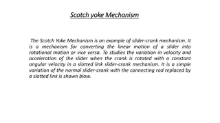
Analysis of Slider-Crank Mechanism and Experimental Data
Slider-crank mechanism analysis involves understanding the transformation of input motion into desired output motion. This mechanism consists of a crank, coupler, slider, and ground link, converting circular motion into linear motion. Experimental procedures involve setting crank angles and recording displacements to calculate theoretical values. Graphs comparing experimental and theoretical data are plotted to visualize piston rod displacement, velocity, and acceleration.

Download Presentation

Please find below an Image/Link to download the presentation.
The content on the website is provided AS IS for your information and personal use only. It may not be sold, licensed, or shared on other websites without obtaining consent from the author. Download presentation by click this link. If you encounter any issues during the download, it is possible that the publisher has removed the file from their server.
E N D
Presentation Transcript
Exp. No. Exp. No. 1 1 : mechanism mechanism 1-1 Slider crank Mechanism : Analysis of Analysis of
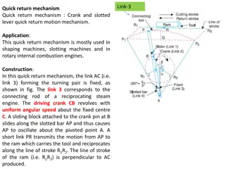
1 1- -1 1 Slider crank Mechanism Slider crank Mechanism A Mechanism is a device which transforms some input motion to some desirable pattern of output motion. The slider-crank mechanism is a simple four bar mechanism in which the rocker is replaced by a slider. Thus the four links in the slider-crank mechanism are: Crank, Coupler/Connecting Rod, Slider and the Ground link. A simple slider-crank mechanism is shown below. A slider crank mechanism converts circular motion of the crank into linear motion of the slider. In order for the crank to rotate fully the condition L> r must be satisfied where r is the crank length is the length of the link connecting crank and slider. A crank is an arm attached at right angles to a rotating shaft by which reciprocating motion is imparted to or received from the shaft. The Slider-Crank mechanism can be used whenever there is a need of converting rotational motion to translational motion. The common applications of slider-crank mechanism are the internal combustion engines, Bull Gear, locomotives, etc.
Procedures Set the crank angle at zero degrees with the help of the angular scale available on the crank and record the piston displacement. Move the crank angle by 30 and record the displacement. Repeat steps 1&2 for one complete revolution of the crank angle. Tabulate your results in the table given. Calculate the theoretical piston rod displacement, velocity and acceleration in the table. Equation of motion : XB=( r+L ) (rcos +Lcos ) 1 Where: r =OA=25mm L=AB=150mm rsin =Lsin 2
Let n=L/r . . XB= r (1-cos +????2 2?) ??= ? ? (sin? +sin2? 2?
Graph: Plot a graph of the experimental piston rod displacement versus crank angle. Plot on a same graph of the theoretical piston rod displacement versus crank angle. Plot a graph of the theoretical piston rod velocity and acceleration versus crank angle.