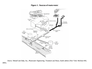
Understanding Primary Clarifiers in Wastewater Treatment

Primary clarifiers are crucial components designed to remove particles with specific settling rates from wastewater. They come in rectangular and circular designs, each with typical dimensions and performance data for BOD and TSS removal. Understanding the design parameters like detention time, overflow rate, and weir load is essential for efficient operation. This article provides insights into the design, operation, and performance of primary clarifiers in wastewater treatment plants.

Download Presentation

Please find below an Image/Link to download the presentation.
The content on the website is provided AS IS for your information and personal use only. It may not be sold, licensed, or shared on other websites without obtaining consent from the author. Download presentation by click this link. If you encounter any issues during the download, it is possible that the publisher has removed the file from their server.
E N D
Presentation Transcript
Primary clarifier are usually designed to remove particles with settling rates of 0.3 0.7 mm/sec. Two common design of primary clarifier, rectangular and circular. Efficiently designed and operated primary sedimentation tank should remove from 50 -70 % of suspended solids and from 25 40% of BOD.
Typical dimensions of primary clarifier Unit Range Typical Rectangular Tank Depth m 3-4.9 4.3 Length m 15-90 24-40 Width m 3-24 4.9-9.8 Sludge collector speed m/min 0.6-1.2 0.9 Circular Tank Depth m 3-4.9 4.3 Diameter m 3-60 12-45 Sludge collector speed rpm 0.02 -0.05 0.03
BOD and TSS removal : Typical performance data for the removal of BOD and TSS in primary sedimentation tank as a function of detention time and concentration are presented in the figure below. These curves are derived from observations of the performance of actual sedimentation tanks. The relationship in the figure can be modeled as follows: ? R= ?+? ? R : expected removal efficiency t: nominal detention time a , b : experimental constants
Typical values of the experimental constants are as follows: a b BOD 0.018 0.02 TSS 0.0075 0.014 Surface loading rates: Sedimentation basins are normaly designed on the basis of surface overflow rate (commonly termed overflow rate) expressed as m3/m2.d. Typically, 30 -50 m3/m2.d is suitable for average flow. It should be emphasized that overflow rate must be set low enough to ensure satisfactory performance at peak rates.
Typical design information Rectangular Circular Detention time (h) 1.5 -2.5 1.5-2.5 Overflow rate (m/h) 1-2.5 1-2.5 Weir load (m3/m.d) 125-500 125-500
Ex/ The average flow rate at a small municipal wastewater treatment plant is 20 000 m3/d. the highest observed peak daily flow rate is 50 000 m3/day. a. Design rectangular primary clarifier with a channel width of 6 m, use a minimum of two clarifiers. b. Calculate the scour velocity to determine if settled material will become resuspended. c. Estimate the BOD and TSS removal at average and peak flow. Use an overflow rate of 40 m3/m2.d at average flow and a side water depth of 4 m.
Solution. a. Design A = Q/SOR A= 20 000/ 40 = 500 m2 L = A/W L= 500/ (2X6)= 41.7 m =42 m. Retention time = volume of the tank / Q Retention time = 2 X (42X6X4) X 24/ 20 000 = 2.4 h. Overflow rate = Q / A Overflow rate = 20 000/ (2 X (6X42)) = 39.7 m3/m2.d
Retention time = volume of the tank / Q Retention time = 2 X (42X6X4) X 24/ 50 000 = 0.97 h. Overflow rate = Q / A Overflow rate = 50 000/ (2 X (6X42)) = 99 m3/m2.d b. Calculate the scour velocity: 8 ? ? ? 1 ? ? ? ????? = 8 0.05 9.81 1.25 1 100 10 6 0.025 = 0.063 m/sec ? ????? =
Calculate the peak flow horizontal velocity to compare to vscour V = Q / A where A: cross-sectional area through which the flow is passes. V= 50 000/2(6X4) = 1041 m/d = 0.012 m/sec. The horizontal velocity value, even at peak flow, is substantially less than the scour velocity. Therefore, settled matter should not be resuspended.
c. estimate the BOD and TSS removal At average flow: ? 2.42 ??? ??????? = ?+? ?= 0.018+0.02 2.42= 36% ? 2.42 ??? ??????? = ?+? ?= 0.0075+0.014 2.42= 58% At peak flow: ? 0.97 ??? ??????? = ?+? ?= 0.018+0.02 0.97= 26% ? 0.97 ??? ??????? = ?+? ?= 0.0075+0.014 0.97= 46%
Ex/ a wastewater containing 250 mg/l suspended solids and 200 mg/l BOD passes through a clarifier. Removal efficiencies of BOD and suspended solids are 37 and 70% respectively at average flow ( 10 000 m3/d) , and 27 and 48% respectively at peak flow ( 30 000 m3/d) . Estimate: a. Effluent BOD and TSS concentration at average and peak flow. b.The maximum and minimum rate of sludge production (assume sludge is 95% water).
Solution: At average flow: Effluent BOD = 200 X (1- 0.37) = 126 mg/L. Effluent TSS = 250 X (1- 0. 7) = 75 mg/L. Solids accumulated=0.7 X 250 X 10 000 X (103/ 106)=1750kg/day Sludge production= 1750/0.05 =3500 kg/day. At peak flow: Effluent BOD = 200 X (1- 0.27) = 146 mg/L. Effluent TSS = 250 X (1- 0. 48) = 130 mg/L. Solids accumulated=0.48 X 250 X 30 000 X (103/ 106)=3600 kg/day Sludge production= 3600/0.05 =72 000 kg/day.