New Holland U80 Loader Landscaper Service Repair Manual Instant Download
Please open the website below to get the complete manualnn//

Download Presentation

Please find below an Image/Link to download the presentation.
The content on the website is provided AS IS for your information and personal use only. It may not be sold, licensed, or shared on other websites without obtaining consent from the author. Download presentation by click this link. If you encounter any issues during the download, it is possible that the publisher has removed the file from their server.
E N D
Presentation Transcript
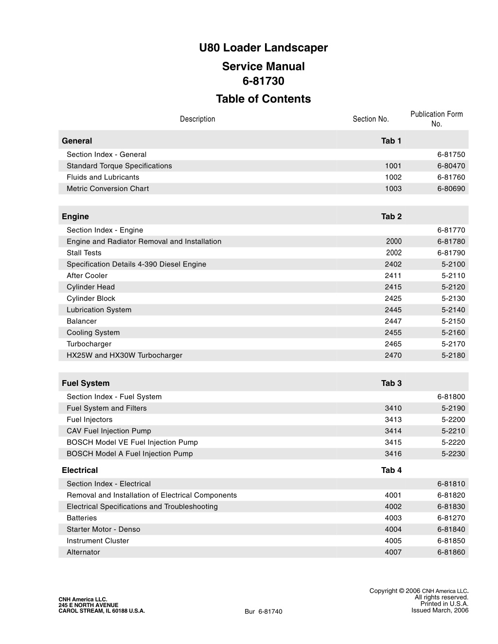
U80 Loader Landscaper Service Manual 6-81730 Table of Contents Publication Form No. Description Section No. General Tab 1 Section Index - General Standard Torque Specifications Fluids and Lubricants Metric Conversion Chart 6-81750 6-80470 6-81760 6-80690 1001 1002 1003 Engine Tab 2 Section Index - Engine Engine and Radiator Removal and Installation Stall Tests Specification Details 4-390 Diesel Engine After Cooler Cylinder Head Cylinder Block Lubrication System Balancer Cooling System Turbocharger HX25W and HX30W Turbocharger 6-81770 6-81780 6-81790 5-2100 5-2110 5-2120 5-2130 5-2140 5-2150 5-2160 5-2170 5-2180 2000 2002 2402 2411 2415 2425 2445 2447 2455 2465 2470 Fuel System Tab 3 Section Index - Fuel System Fuel System and Filters Fuel Injectors CAV Fuel Injection Pump BOSCH Model VE Fuel Injection Pump BOSCH Model A Fuel Injection Pump 6-81800 5-2190 5-2200 5-2210 5-2220 5-2230 3410 3413 3414 3415 3416 Electrical Tab 4 Section Index - Electrical Removal and Installation of Electrical Components Electrical Specifications and Troubleshooting Batteries Starter Motor - Denso Instrument Cluster Alternator 6-81810 6-81820 6-81830 6-81270 6-81840 6-81850 6-81860 4001 4002 4003 4004 4005 4007 Copyright 2006 CNH America LLC. All rights reserved. CNH America LLC. 245 E NORTH AVENUE CAROL STREAM, IL 60188 U.S.A. Printed in U.S.A. Issued March, 2006 Bur 6-81740
Table of Contents Publication Form No. Description Section No. Steering Tab 5 Section Index - Steering Removal and Installation of Steering Components Steering Specifications, Pressure Checks and Troubleshooting Steering Control Valve Steering Cylinders Front Axle - Two Wheel Drive Front Axle - Four Wheel Drive 6-81870 6-81880 6-81890 6-81900 6-81910 6-81920 6-81930 5001 5002 5003 5004 5005 5006 Power Train Tab 6 Section Index - Power Train Removal and Installation of Power Train Components Standard Transmission Specifications, Pressure Checks and Troubleshooting Wheels and Tires Rear Axle and Planetaries Standard Transmission 6-81940 6-81950 6-81960 6-81970 6-81980 5-1000 6001 6002 6003 6004 6007 Brakes Tab 7 Section Index - Brakes Removal and Installation of Brake Components Master Cylinder 5-1010 5-1020 5-1030 7001 7003 Hydraulics Tab 8 Section Index - Hydraulics Removal and Installation of Hydraulic Components Hydraulic Specifications, Troubleshooting, and Pressure Checks Cleaning the Hydraulic System Hydraulic Pump Loader Control Valve Cylinders Three Point Hitch Control Valve Accumulator for Machines with Optional Ride Control Solenoid Valve for Machines with Optional Ride Control Flow Control Valve Lock Valve flow Control Priority Valve 5-1040 5-1050 5-1060 5-1070 5-1080 5-1090 5-1100 5-1110 5-1120 5-1130 5-1140 5-1150 5-1160 8001 8002 8003 8004 8005 8006 8007 8009 8010 8011 8012 8013 Mounted Equipment Tab 9 Section Index - Mounted Equipment Pedals and Levers Air Conditioning Troubleshooting For Systems With R-134a Refrigerant Air Conditioning System Service For Systems With R-134a Refrigerant Air Conditioning Components Service For Systems With R-134a Refrigerant Loader ROPS Cab and Canopy Pedestal Seat 5-1170 5-1180 5-1190 5-1200 5-1210 5-1220 5-1230 5-1240 9001 9002 9004 9005 9006 9007 9009 Bur 6-81740 Issued 3-06 Printed in U.S.A.
Table of Contents Publication Form No. Description Section No. Schematics Electric Schematic and Hydraulic Schematic Foldout In Rear Pocket 5-1250 NOTE: CNH Corporation reserves the right to make improvements in design or changes in specifications at any time without incurring any obligation to install them on units previously sold. Bur 6-81740 Issued 3-06 Printed in U.S.A.
https://www.ebooklibonline.com Hello dear friend! Thank you very much for reading. Enter the link into your browser. The full manual is available for immediate download. https://www.ebooklibonline.com
SECTION INDEX GENERAL Section Title Section Number Standard Torque Specifications . . . . . . . . . . . . . . . . . . . . . . . . . . . . . . . . . . . . . . . . . . . . . . . . . . . . . . . . . . . . 1001 Fluid and Lubricants . . . . . . . . . . . . . . . . . . . . . . . . . . . . . . . . . . . . . . . . . . . . . . . . . . . . . . . . . . . . . . . . . . . . . 1002 Metric Conversion Chart . . . . . . . . . . . . . . . . . . . . . . . . . . . . . . . . . . . . . . . . . . . . . . . . . . . . . . . . . . . . . . . . . . 1003 Copyright 2006 CNH America LLC. All rights reserved. CNH America LLC. 245 E NORTH AVENUE CAROL STREAM, IL 60188 U.S.A. Printed in U.S.A. Issued March, 2006 Bur 6-81750
1001-3 TORQUE SPECIFICATIONS - DECIMAL HARDWARE Use the torques in this chart when special torques are not given. These torques apply to fasteners with both UNC and UNF threads as received from suppliers dry, or when lubricated with engine oil. Not applicable if special graphities, Molydisulfide greases, or other extreme pressure lubricants are used. Grade 8 Bolts, Nuts, and Studs Pound- Inches 144 to 180 288 to 348 540 to 648 Newton metres 16 to 20 33 to 39 61 to 73 Size 1/4 inch 5/16 inch 3/8 inch Grade 5 Bolts, Nuts, and Studs Pound- Inches 108 to 132 204 to 252 420 to 504 Newton metres 12 to 15 23 to 28 48 to 57 Pound- Feet 70 to 84 110 to 132 160 to 192 220 to 264 380 to 456 600 to 720 900 to 1080 1280 to 1440 1820 to 2000 2380 to 2720 3160 to 3560 Newton metres 95 to 114 149 to 179 217 to 260 298 to 358 515 to 618 814 to 976 1220 to 1465 1736 to 1953 2468 to 2712 3227 to 3688 4285 to 4827 Size 1/4 inch 5/16 inch 3/8 inch Size 7/16 inch 1/2 inch 9/16 inch 5/8 inch 3/4 inch 7/8 inch 1.0 inch 1-1/8 inch 1-1/4 inch 1-3/8 inch 1-1/2 inch NOTE: Use thick nuts with Grade 8 bolts. Pound- Feet 54 to 64 80 to 96 110 to 132 150 to 180 270 to 324 400 to 480 580 to 696 800 to 880 1120 to 1240 1460 to 1680 1940 to 2200 Newton metres 73 to 87 109 to 130 149 to 179 203 to 244 366 to 439 542 to 651 787 to 944 1085 to 1193 1519 to 1681 1980 to 2278 2631 to 2983 Size 7/16 inch 1/2 inch 9/16 inch 5/8 inch 3/4 inch 7/8 inch 1.0 inch 1-1/8 inch 1-1/4 inch 1-3/8 inch 1-1/2 inch Bur 6-80470 Issued 1-06 Printed in U.S.A.
1001-4 TORQUE SPECIFICATIONS - METRIC HARDWARE Use the following torques when specifications are not given. Grade 10.9 Bolts, Nuts, and Studs These values apply to fasteners with coarse threads as received from supplier, plated or unplated, or when lubricated with engine oil. These values do not apply if graphite or Molydisulfide grease or oil is used. 10.9 Pound- Inches 36 to 48 84 to 96 132 to 156 324 to 384 Newton metres 4 to 5 9 to 11 15 to 18 37 to 43 Size M4 M5 M6 M8 Grade 8.8 Bolts, Nuts, and Studs 8.8 Pound- Inches 24 to 36 60 to 72 96 to 108 228 to 276 456 to 540 Newton metres 3 to 4 7 to 8 11 to 12 26 to 31 52 to 61 Pound- Feet 54 to 64 93 to 112 149 to 179 230 to 280 450 to 540 780 to 940 1470 to 1770 2580 to 3090 Newton metres 73 to 87 125 to 150 200 to 245 310 to 380 610 to 730 1050 to 1275 2000 to 2400 3500 to 4200 Size M4 M5 M6 M8 M10 Size M10 M12 M14 M16 M20 M24 M30 M36 Pound- Feet 66 to 79 106 to 127 160 to 200 320 to 380 500 to 600 920 to 1100 1600 to 1950 Newton metres 90 to 107 144 to 172 217 to 271 434 to 515 675 to 815 1250 to 1500 2175 to 2600 Size M12 M14 M16 M20 M24 M30 M36 Grade 12.9 Bolts, Nuts, and Studs 12.9 Usually the torque values specified for grade 10.9 fasteners can be used satisfactorily on grade 12.9 fasteners. Bur 6-80470 Issued 1-06 Printed in U.S.A.
1001-5 TORQUE SPECIFICATIONS - STEEL HYDRAULIC FITTINGS 37 Degree Flare Fitting Straight Threads with O-ring Tube OD Hose ID 1/4 inch 6.4 mm 5/16 inch 7.9 mm 3/8 inch 9.5 mm 1/2 inch 12.7 mm 5/8 inch 15.9 mm Thread Size 7/16-20 Pound- Inches 72 to 144 Newton metres 8 to 16 Tube OD Hose ID 1/4 inch 6.4 mm 5/16 inch 7.9 mm 3/8 inch 9.5 mm 1/2 inch 12.7 mm Thread Size 7/16-20 Pound- Inches 144 to 228 Newton metres 16 to 26 1/2-20 96 to 192 11 to 22 1/2-20 192 to 300 22 to 34 9/16-18 120 to 300 14 to 34 9/16-18 300 to 480 34 to 54 3/4-16 180 to 504 20 to 57 3/4-16 540 to 804 57 to 91 7/8-14 300 to 696 34 to 79 Tube OD Hose ID 5/8 inch 15.9 mm 3/4 inch 19.0 mm 7/8 inch 22.2 mm 1.0 inch 25.4 mm 1-1/4 inch 31.8 mm 1-1/2 inch 38.1 mm Thread Size 7/8-14 Pound- Feet 58 to 92 Newton metres 79 to 124 Tube OD Hose ID 3/4 inch 19.0 mm 7/8 inch 22.2 mm 1.0 inch 25.4 mm 1-1/4 inch 31.8 mm 1-1/2 inch 38.1 mm Thread Size 1-1/16-12 Pound- Feet 40 to 80 Newton metres 54 to 108 1-1/16-12 80 to 128 108 to 174 1-3/16-12 60 to 100 81 to 135 1-3/16-12 100 to 160 136 to 216 1-5/16-12 117 to 187 159 to 253 1-5/16-12 75 to 117 102 to 158 1-5/8-12 125 to 165 169 to 223 1-5/8-12 165 to 264 224 to 357 1-7/8-12 250 to 400 339 to 542 1-7/8-12 210 to 250 285 to 338 Split Flange Mounting Bolts Pound- Inches 180 to 240 240 to 300 420 to 540 Newton metres 20 to 27 27 to 34 47 to 61 Size 5/16-18 3/8-16 7/16-14 Pound- Feet 55 to 65 140 to 150 Newton metres 74 to 88 190 to 203 Size 1/2-13 5/8-11 Bur 6-80470 Issued 1-06 Printed in U.S.A.
1001-6 TORQUE SPECIFICATIONS - STEEL HYDRAULIC FITTINGS O-ring Boss End Fitting or Lock Nut O-ring Face Seal End Nom. SAE Dash Size -4 Thread Size 9/16-18 Pound- Inches 120 to 144 Newton metres 14 to 16 Thread Size 7/16-20 Pound- Inches 204 to 240 Newton metres 23 to 27 Tube OD 1/4 inch 6.4 mm 3/8 inch 9.5 mm 1/2 inch 12.7 mm -6 11/16-16 216 to 240 24 to 27 9/16-18 300 to 360 34 to 41 -8 13/16-16 384 to 480 43 to 54 3/4-16 540 to 600 61 to 68 Thread Size 7/8-14 Pound- Feet 60 to 65 Newton metres 81 to 88 -10 5/8 inch 15.9 mm 1-14 552 to 672 62 to 76 Nom. SAE Dash Size -12 1-1/16-12 85 to 90 115 to 122 Thread Size 1-3/16-12 Pound- Feet 65 to 80 Newton metres 90 to 110 1-3/16-12 95 to 100 129 to 136 Tube OD 3/4 inch 19.0 mm 7/8 inch 22.2 mm 1.0 inch 25.4 mm 1-1/4 inch 31.8 mm 1-1/2 inch 38.1 mm 1-5/16-12 115 to 125 156 to 169 -14 1-3/16-12 65 to 80 90 to 110 1-5/8-12 150 to 160 203 to 217 -16 1-7/16-12 92 to 105 125 to 140 1-7/8-12 190 to 200 258 to 271 -20 1-11/16-12 125 to 140 170 to 190 -24 2-12 150 to 180 200 to 254 Bur 6-80470 Issued 1-06 Printed in U.S.A.
Section 2000 ENGINE AND RADIATOR REMOVAL AND INSTALLATION 2000 Copyright 2006 CNH America LLC. All rights reserved. CNH America LLC. 245 E NORTH AVENUE CAROL STREAM, IL 60188 U.S.A. Printed in U.S.A. Issued March, 2006 Bur 6-81780
2000-3 SPECIAL TOOLS B430842 CAS1690A SPECIFICATIONS ENGINE CRANKCASE Capacity with filter change .......................................................................................... 11 litres (11.6 U.S. quarts) FUEL TANK Capacity .................................................................................................................... 115 litres (30.3 U.S. gallons) Usable fuel ................................................................................................................ 112 litres (29.5 U.S. gallons) Specifications ............................................................................................................. See the Operator s Manual COOLING SYSTEM Capacity .................................................................................................................... 15.8 litres (16.7 U.S. quarts) Specifications ............................................................................................... 50% water and 50% ethylene glycol HYDRAULIC RESERVOIR REFILL Total system .................................................................................................................70 litres (18.5 U.S. gallons) Capacity with filter change ............................................................................................ 49 litres (13 U.S. gallons) Capacity without filter change .....................................................................................47 litres (12.5 U.S. gallons) Specifications ..................................................................................................New Holland AMBRA Master-Tran Bur 6-81780 Issued 3-06 Printed in U.S.A.
2000-4 RADIATOR REMOVAL IMPORTANT: disconnected hoses and wires. Close disconnected hoses and fittings with caps and plugs to prevent hydraulic system contamination. Put identification tags on all 4. Slowly remove the radiator cap. Install a hose on the drain valve and drain the radiator into a clean container that holds approximately 17 litres (18 U.S. quarts). NOTE: The photos in this procedure may be different from your machine and are for reference only. 1. Park the machine on a level surface. Raise the loader and lock the support strut (1) to hold the loader. Stop the engine and apply the parking brake. BD01B322 NOTE: During installation, fill the radiator and coolant reservoir completely. See page 3 for coolant specifications. Start and run the engine until the coolant is at operating temperature. Stop the engine and check for leakage. When the coolant is cold, check the coolant reservoir level. Add coolant as required. 1 BD01H021 5. Disconnect the overflow hose (1) from the radiator neck. Loosen the clamp and disconnect the upper radiator hose (2). 2. Remove the side panels from the machine. 2 1 BD01H023 3. Remove the hood from the machine. BD01D045 Bur 6-81780 Issued 3-06 Printed in U.S.A.
2000-5 6. Loosen the clamp (1) and disconnect the lower radiator hose. 8. See the illustrations beginning on page 12 for the following steps. 9. Remove the hardware from the fan shroud. Move the fan shroud away from the radiator. NOTE: During installation apply Dow 737 RTV sealant to the fan shroud to form a seal between the fan shroud and the radiator. During installation tighten the bolts to a torque of 5 to 6.2 Nm (45 to 55 pound-inches). 1 10. Remove the hardware that fastens the upper brackets to the radiator. Remove the hardware and the upper brackets from the radiator shroud. 11. Remove the screen from the radiator shroud. 12. Remove the radiator shroud from the machine. BD01H112 7. Remove the bolts (1), spacers, washers, and coolant reservoir from the machine. 13. Fasten lifting equipment to the oil cooler that will hold the oil cooler in place when the radiator is removed. 14. Remove the hardware that fastens the oil cooler and if equipped the fuel cooler to the radiator. Lift the radiator straight up and remove the radiator from the machine. 1 NOTE: Installation of the radiator is the reverse of removal. 1 BD01H032 NOTE: During installation tighten the bolts to a torque of 5 to 6 Nm (44 to 53 pound-inches). Bur 6-81780 Issued 3-06 Printed in U.S.A.
2000-6 ENGINE REMOVAL IMPORTANT: disconnected hoses and wires. Close disconnected hoses and fittings with caps and plugs to prevent hydraulic system contamination. Put identification tags on all 4. Remove the battery cover from the hydraulic reservoir. If the machine has only one battery, disconnect the negative battery cable from the battery. NOTE: The photos in this procedure may be different from your machine and are for reference only. 1. Park the machine on a level surface. Raise the loader and lock the support strut (1) to hold the loader. Stop the engine and apply the parking brake. 1 BD01H148 5. If the machine has two batteries, remove the terminal nuts (1). Remove the jumper cable (2) from the batteries. Remove the negative ground strap (3) from the battery. 1 3 BD01H021 2. Remove the side panels from the machine. 1 2 1 BD00H122 6. Drain the oil from the hydraulic reservoir. NOTE: During installation fill the hydraulic reservoir with the oil specified in section 1002 of this manual. BD01H023 3. Put the battery disconnect switch in the OFF position. Bur 6-81780 Issued 3-06 Printed in U.S.A.
2000-7 14. Disconnect the hoses from both sides of the hydraulic oil cooler. Identify each hose with its location of removal. Cap the fittings and plug the hoses. 7. Slowly remove the radiator cap. Install a hose on the drain valve and drain the radiator into a clean container that holds approximately 17 litres (18 U.S. quarts). BD01B322 GS99D801 NOTE: During installation, fill the radiator and coolant reservoir completely with coolant. See page 1-3 for coolant specifications. Start and run the engine until the coolant is at operating temperature. Stop the engine and check for leakage. When the coolant is cold, check the coolant reservoir level. Add coolant as required. 8. See the illustrations beginning on page 12 for the following steps. 9. Loosen the clamp and disconnect the upper radiator hose (2). 10. Loosen the clamp (1) and disconnect the lower radiator hose. 11. Remove the hardware from the fan shroud. Move the fan shroud away from the radiator. 12. Remove the baffle plate from the machine. 13. Remove the screen from the front of the machine. GS99D802 15. Fasten lifting equipment to the radiator shroud. Remove the bolts (2) and washers that fasten the radiator shroud to the frame. NOTE: During installation tighten the bolts (2) to a torque of 434 to 515 Nm (320 to 380 pound-feet). 16. Remove the radiator shroud, radiator, oil cooler and if equipped with turbocharger the fuel cooler as an assembly. 17. Remove the fan shroud from the fan. Bur 6-81780 Issued 3-06 Printed in U.S.A.
2000-8 18. Disconnect the hoses (1) from the Left-hand side of the pump. 21. Loosen the clip for the exhaust pipe at the muffler. Remove the exhaust pipe from the muffler. 1 1 BD01B314 19. Remove the bolts and lock washers that fasten the fitting (1) on the Right-hand side of the pump. BD01B306 22. Remove the tie strap. Disconnect the electrical connectors for the air restriction indicator. 1 BD01H065 23. If the machine is equipped with turbocharger, loosen the clamp on the air cleaner hose at the turbocharger. Disconnect the air cleaner hose from the turbocharger. BD01B315 20. Loosen and remove the bolts that fasten the equipment pump to the pump mounting bracket. Remove the equipment pump from the machine. BD01B323 BD01B328 Bur 6-81780 Issued 3-06 Printed in U.S.A.
2000-9 24. If the machine is not equipped with turbocharger, loosen the clamp on the air cleaner hose at the intake manifold. Disconnect the air cleaner hose from the intake manifold. 27. Disconnect the throttle rod (1). Disconnect the wiring clamp (2). Disconnect the wire from the oil pressure sender (3). 1 3 2 BD01B375 28. Disconnect the throttle cable from the mounting bracket (1). BD01B366 25. If the machine has ether injection, remove the tie straps (1) and sleeve (2) from the tube (3) and wire (4). Disconnect the tube (3) and the wire (4). 4 3 1 1 2 BD01B377 29. Disconnect the fuel lines (1) and (2). BP9502303 26. Disconnect the electrical connector for the fuel injection pump (1). 1 1 2 BD01B377 BD01B365 Bur 6-81780 Issued 3-06 Printed in U.S.A.
Suggest: If the above button click is invalid. Please download this document first, and then click the above link to download the complete manual. Thank you so much for reading
2000-10 30. Disconnect the coolant temperature sender (1) and coolant temperature switch (2). 33. Remove the bolts, flat washers, and nuts from the front engine mount. 2 1 BP9502298 BP9502310 NOTE: During installation, tighten the self-locking nuts to 70 to 90 Nm (51 to 66 pound-feet). See the illustration on page 1-23 for correct installation. 31. Remove the harness clamps (1). Disconnect the wires (2) from the alternator. 1 34. Connect lifting equipment to the lifting eyes on the engine to hold the engine in place. NOTE: There are six bolts with lock washers that fasten the flywheel to the torque converter. The engine must be rotated to align each bolt with the access hole in the flywheel housing at the left side of the engine. 2 1 35. Remove the plastic plug from the flywheel housing. Remove the hose from the bracket and remove the cover and gasket from the access hole for the bolts. BP9502296 36. Install the CAS1690A tool to turn the flywheel for access to the bolts. 32. Disconnect the ground strap (1). Disconnect the wires (2) from the starter. 1 2 2 BP9502299 BP9502316 Bur 6-81780 Issued 3-06 Printed in U.S.A.
https://www.ebooklibonline.com Hello dear friend! Thank you very much for reading. Enter the link into your browser. The full manual is available for immediate download. https://www.ebooklibonline.com