New Holland TD95 Tractor Service Repair Manual Instant Download
Please open the website below to get the complete manualnn//

Download Presentation

Please find below an Image/Link to download the presentation.
The content on the website is provided AS IS for your information and personal use only. It may not be sold, licensed, or shared on other websites without obtaining consent from the author. Download presentation by click this link. If you encounter any issues during the download, it is possible that the publisher has removed the file from their server.
E N D
Presentation Transcript
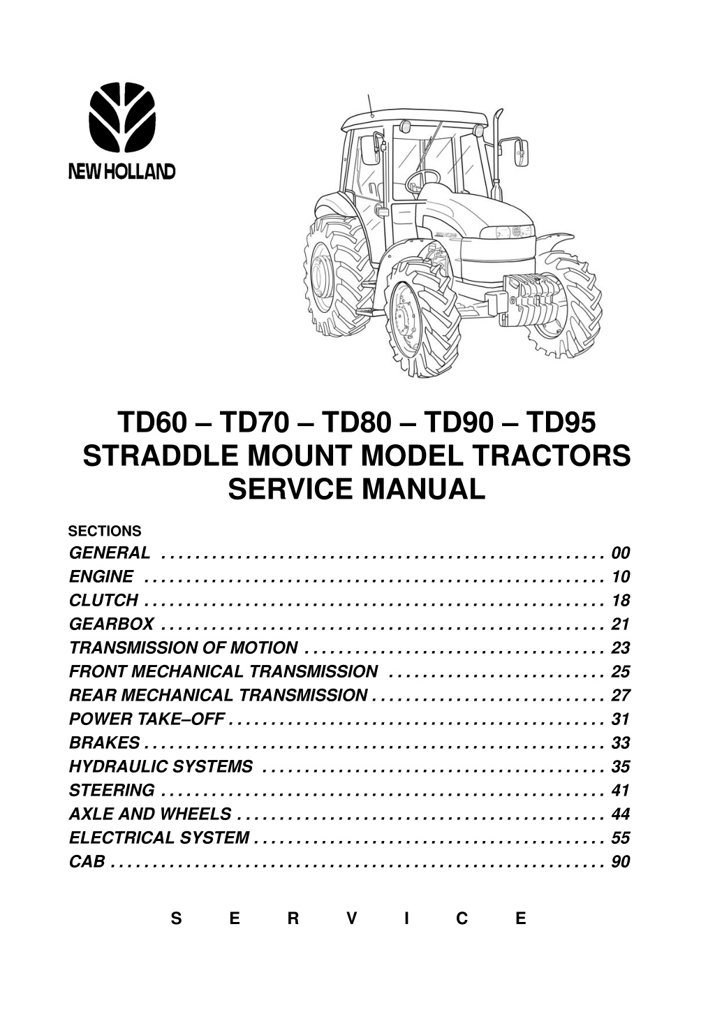
TD60 TD70 TD80 TD90 TD95 STRADDLE MOUNT MODEL TRACTORS SERVICE MANUAL SECTIONS GENERAL ENGINE CLUTCH GEARBOX TRANSMISSION OF MOTION FRONT MECHANICAL TRANSMISSION REAR MECHANICAL TRANSMISSION POWER TAKE OFF BRAKES . . . . . . . . . . . . . . . . . . . . . . . . . . . . . . . . . . . . . . . . . . . . . . . . . . . . . . . HYDRAULIC SYSTEMS . . . . . . . . . . . . . . . . . . . . . . . . . . . . . . . . . . . . . . . . . STEERING . . . . . . . . . . . . . . . . . . . . . . . . . . . . . . . . . . . . . . . . . . . . . . . . . . . . . AXLE AND WHEELS . . . . . . . . . . . . . . . . . . . . . . . . . . . . . . . . . . . . . . . . . . . . ELECTRICAL SYSTEM . . . . . . . . . . . . . . . . . . . . . . . . . . . . . . . . . . . . . . . . . . CAB . . . . . . . . . . . . . . . . . . . . . . . . . . . . . . . . . . . . . . . . . . . . . . . . . . . . . . . . . . . . . . . . . . . . . . . . . . . . . . . . . . . . . . . . . . . . . . . . . . . . . . . . . . . . . . . . . . . . . . . . . . . . . . . . . . . . . . . . . . . . . . . . . . . . . . . . . . . . . . . . . . . . . . . . . . . . . . . . . . . . . . . . . . . . . . . . . . . . . . . . . . . . . . . . . . . . . . . . . . . . . . . . . . . . . . . . . . . . . . . . . . . . . . . . . . . . . . . . . . . . . . . . . . . . . . . . . . . . . . . . . . . . . . . . . . . . . . . . . . . . . . . . . . . . . . . 00 10 18 21 23 25 27 31 33 35 41 44 55 90 . . . . . . . . . . . . . . . . . . . . . . . . . . . . . . . . . . . . . . . . . . . . . . . . . . . . . . . . . . . . . . . . . . . . . . . . . . . . . . . . . . . . . . . . . . . . . . . . . . . S E R V I C E
INTRODUCTION This manual is divided into sections identified by two figure numbers. Each section has independent page numbering. For ease of reference, these sections have the same numbers and names as the Repairs Rate Book sections. The different sections can easily be found by consulting the table of contents on the following pages. The document number of the manual and the edition/update dates are given at the bottom of each page. Pages updated in the future will be identified by the same document number followed by a two figure update number (for example: 1st update 603.54.331.01; 2nd update 603.54.331.02; etc.) and the corresponding is- sue date. These pages will be supplemented by a reprint of the updated contents page. The information contained in this manual was current on the date printed on each section. As NEW HOLLAND constantly improves its product range, some information may be out of date subsequent to modifications im- plemented for technical or commercial reasons or to meet legal requirements in different countries. In the event of conflicting information, consult the NEW HOLLAND Sales and Service Departments. IMPORTANT WARNINGS All maintenance and repair work described in this manual must be performed exclusively by NEW HOLLAND service technicians in strict accordance with the instructions given and using any specific tools necessary. Anyone who performs the operations described herein without strictly following the instructions is personally responsible for resulting injury or damage to property. The Manufacturer and all organisations belonging to the Manufacturer s distribution network, including but not restricted to national, regional or local distributors, will accept no responsibility for personal injury or dam- age to property caused by abnormal function of parts and/or components not approved by the Manufacturer, including those used for maintenance and/or repair of the product manufactured or marketed by the Manufac- turer. In any case, the product manufactured or marketed by the Manufacturer is covered by no guarantee of any kind against personal injury or damage to property caused by abnormal function of parts and/or components not approved by the Manufacturer. TEXT AND ILLUSTRATIONS ARE THE PROPERTY OF NEW HOLLAND ??????????????? No part of the text or illustrations may be reproduced PRINTED IN ????? NEW HOLLAND ????????. ?????????????????????????????????? SERVICE Technical Publications & Special Tools Print no. ???.??.???.?? 06 2002
NEW HOLLAND Repair Manual TD Straddle Mount Series Tractors CONTENTS GENERAL SECTION 00 General Instructions and Health and Safety Chapter 1 Section Description Page General instructions Notes for spare parts Notes for equipment Safety rules Consumables . . . . . . . . . . . . . . . . . . . . . . . . . . . . . . . . . . . . . . . . . . . . . . . . . . . . . . . . . . . . . . . . . . . . . . . . . . . . . . . . . . . . . . . . . . . . . . . . . . . . . . . . . . . . . . . . . . . . . . . . . . . . . . . . . . . . . . . . . . . . . . . . . . . . . . . . . . . . . . . . . . . . . . . . . . . . . . . . . . . . . . . . . . . . . . . . . . . . . . . . . . . . . . . . . . . . . . . . . . . . . . . . . . . . . . . . . . . . . . . . . . . . . . . . . . . . . . . . . . . . . . . . . . . . . . . . . . . . . . . . . . . . . . . . . . . . . . . . . . . . . . . . . . . . . . . . . . . . 1 2 2 3 6 00 000 ENGINE SECTION 10 Engine System Chapter 1 Section Description Page General specifications Data . . . . . . . . . . . . . . . . . . . . . . . . . . . . . . . . . . . . . . . . . . . . . . . . . . . . . . . . . . . . . . . . . . . . . . . . . . Torque settings . . . . . . . . . . . . . . . . . . . . . . . . . . . . . . . . . . . . . . . . . . . . . . . . . . . . . . . . . . . . . . . Tools . . . . . . . . . . . . . . . . . . . . . . . . . . . . . . . . . . . . . . . . . . . . . . . . . . . . . . . . . . . . . . . . . . . . . . . . Cross sectional views . . . . . . . . . . . . . . . . . . . . . . . . . . . . . . . . . . . . . . . . . . . . . . . . . . . . . . . . . Lubrication and cooling system diagrams . . . . . . . . . . . . . . . . . . . . . . . . . . . . . . . . . . . . . . . . Troubleshooting . . . . . . . . . . . . . . . . . . . . . . . . . . . . . . . . . . . . . . . . . . . . . . . . . . . . . . . . . . . . . . Removal Installation Overhaul . . . . . . . . . . . . . . . . . . . . . . . . . . . . . . . . . . . . . . . . . . . . . . . Checks, dimensions and repairs . . . . . . . . . . . . . . . . . . . . . . . . . . . . . . . . . . . . . . . . . . . . . . . . . . . . . . . . . . . . . . . . . . . . . . . . . . . . . . . . . . . . . . . . . . . . . . . . . . . . . . . . . . . 2 5 10 000 24 25 28 32 35 39 80 10 001 CLUTCH SECTION 18 Clutches Chapter 1 Section Description Page General Characteristics Tightening Torques Tools . . . . . . . . . . . . . . . . . . . . . . . . . . . . . . . . . . . . . . . . . . . . . . . . . . . . . . . . . . . . . . . . . . . . . . . . . . Sectional views . . . . . . . . . . . . . . . . . . . . . . . . . . . . . . . . . . . . . . . . . . . . . . . . . . . . . . . . . . . . . . Clutch Troubleshooting . . . . . . . . . . . . . . . . . . . . . . . . . . . . . . . . . . . . . . . . . . . . . . . . . . . . . . . . . . Removal Refitting . . . . . . . . . . . . . . . . . . . . . . . . . . . . . . . . . . . . . . . . . . . . . . . . . . . . . . . . . Overhaul . . . . . . . . . . . . . . . . . . . . . . . . . . . . . . . . . . . . . . . . . . . . . . . . . . . . . . . . . . . . . . . . . . . . . . . . . . . . . . . . . . . . . . . . . . . . . . . . . . . . . . . . . . . . . . . . . . . . . . . . . . . . . . . . . . . . . . . . . . . . . . . . . . . . . . . . . . . . . . . . . . . . . . . . . . . . . . . . . . . . . . . . . 1 2 3 18 000 3 6 7 8 15 16 19 18 110 10 18 110 30
https://www.ebooklibonline.com Hello dear friend! Thank you very much for reading. Enter the link into your browser. The full manual is available for immediate download. https://www.ebooklibonline.com
Checks, measurements and repairs Adjustments . . . . . . . . . . . . . . . . . . . . . . . . . . . . . . . . . . . . . . . . . . . . . . . . . . . . . . . . . . . . . . . . . . . . . . . . . . . . . . . . . . . . . . . . . . . . . . . . . . . . . . . . . 20 21 22 23 18 100 40 GEARBOX SECTION 21 Mechanical Transmission (12x4) Chapter 1 Section Description Page Main data Tightening torques Tools . . . . . . . . . . . . . . . . . . . . . . . . . . . . . . . . . . . . . . . . . . . . . . . . . . . . . . . . . . . . . . . . . . . . . . . . . . Section views . . . . . . . . . . . . . . . . . . . . . . . . . . . . . . . . . . . . . . . . . . . . . . . . . . . . . . . . . . . . . . . . . . Description and operation . . . . . . . . . . . . . . . . . . . . . . . . . . . . . . . . . . . . . . . . . . . . . . . . . . . . . . . . Fault diagnosis . . . . . . . . . . . . . . . . . . . . . . . . . . . . . . . . . . . . . . . . . . . . . . . . . . . . . . . . . . . . . . . . . Removal Refitting . . . . . . . . . . . . . . . . . . . . . . . . . . . . . . . . . . . . . . . . . . . . . . . . . . . . . . . . . . . . . . . . . . . . . . . . . . . . . . . . . . . . . . . . . . . . . . . . . . . . . . . . . . . . . . . . . . . . . . . . . . . . . . . . . . . . . . . . . . . . . . . . . . . . . . . . . . . . . . . . . . . . . . . . . . . . . . . . . . . . . . . 1 2 3 5 8 8 21 000 see sect 27 21 110 Reverser (12x12) Chapter 2 Section Description Page Main data Tightening torques Tools . . . . . . . . . . . . . . . . . . . . . . . . . . . . . . . . . . . . . . . . . . . . . . . . . . . . . . . . . . . . . . . . . . . . . . . . . . Section views . . . . . . . . . . . . . . . . . . . . . . . . . . . . . . . . . . . . . . . . . . . . . . . . . . . . . . . . . . . . . . . . . . Description and operation . . . . . . . . . . . . . . . . . . . . . . . . . . . . . . . . . . . . . . . . . . . . . . . . . . . . . . . . Fault diagnosis . . . . . . . . . . . . . . . . . . . . . . . . . . . . . . . . . . . . . . . . . . . . . . . . . . . . . . . . . . . . . . . . . Removal Refitting . . . . . . . . . . . . . . . . . . . . . . . . . . . . . . . . . . . . . . . . . . . . . . . . . . . . . . . . . . . . . . . . . . . . . . . . . . . . . . . . . . . . . . . . . . . . . . . . . . . . . . . . . . . . . . . . . . . . . . . . . . . . . . . . . . . . . . . . . . . . . . . . . . . . . . . . . . . . . . . . . . . . . . . . . . . . . . . . . . . . . . . . . . . . . . . . . . 1 2 3 3 5 5 6 21 000 21 110 Reverser and Creeper (20x12) Chapter 3 Section Description Page Main data Tightening torques Tools . . . . . . . . . . . . . . . . . . . . . . . . . . . . . . . . . . . . . . . . . . . . . . . . . . . . . . . . . . . . . . . . . . . . . . . . . . Section views . . . . . . . . . . . . . . . . . . . . . . . . . . . . . . . . . . . . . . . . . . . . . . . . . . . . . . . . . . . . . . . . . . Description and operation . . . . . . . . . . . . . . . . . . . . . . . . . . . . . . . . . . . . . . . . . . . . . . . . . . . . . . . . Fault diagnosis . . . . . . . . . . . . . . . . . . . . . . . . . . . . . . . . . . . . . . . . . . . . . . . . . . . . . . . . . . . . . . . . . Removal Refitting . . . . . . . . . . . . . . . . . . . . . . . . . . . . . . . . . . . . . . . . . . . . . . . . . . . . . . . . . . . . . . . . . . . . . . . . . . . . . . . . . . . . . . . . . . . . . . . . . . . . . . . . . . . . . . . . . . . . . . . . . . . . . . . . . . . . . . . . . . . . . . . . . . . . . . . . . . . . . . . . . . . . . . . . . . . . . . . . . . . . . . . . . . . . . . . . . . 1 2 3 4 6 6 7 21 000 21 110 DRIVE LINES SECTION 23 Drive Lines Chapter 1 Section Description Page Main specification Torque settings and Tools Cross Sectional views Transmission shafts and guard (Disassembly Assembly) Drive gear housing (Removal Installation) Drive gear housing removed (Disassembly Assembly) . . . . . . . . . . . . . . . . . . . . . . . . . . . . . . . . . . . . . . . . . . . . . . . . . . . . . . . . . . . . . . . . . . . . . . . . . . . . . . . . . . . . . . . . . . . . . . . . . . . . . . . . . . . . . . . . . . . . . . . . . . . . . . . . . . . . . . . . . . . . . . . . . . . . . . . . . . . . . . . . . . . . . . . . . . . . . . . . . 1 2 3 4 23 000 . . . . . . . . . . . . . . . . . . . . . . . . . . . . . . . . . . . . . . . . . . . . . . . . . . . . . . . . . . . . . . . . . . . . . . . . . . . . . . . . . . . . . . . . . . . . . 23 101 26 23 101 40 23 101 42 5 6 7
FRONT AXLE MECHANICAL TRANSMISSION SECTION 25 Front Axle Mechanical Transmission Chapter 1 Section Description Page Main data Tightening torques Tools . . . . . . . . . . . . . . . . . . . . . . . . . . . . . . . . . . . . . . . . . . . . . . . . . . . . . . . . . . . . . . . . . . . . . . . . . . Cross sectional views . . . . . . . . . . . . . . . . . . . . . . . . . . . . . . . . . . . . . . . . . . . . . . . . . . . . . . . . . . . Description and operation . . . . . . . . . . . . . . . . . . . . . . . . . . . . . . . . . . . . . . . . . . . . . . . . . . . . . . . . Complete front axle. Removal Installation . . . . . . . . . . . . . . . . . . . . . . . . . . . . . . . . . . . . . . Front axle. Removal Installation . . . . . . . . . . . . . . . . . . . . . . . . . . . . . . . . . . . . . . . . . . . . . . Steering knuckle bearing pins. Replacement Stub axle adjustment . . . . . . . . . . . . . . . . . . . . . . . . . . . . . . . . . . . . . . . . . . . . . . . . . . . . . . . . . . Wheel hub bearing adjustment . . . . . . . . . . . . . . . . . . . . . . . . . . . . . . . . . . . . . . . . . . . . . . . . . Bevel drive adjustment . . . . . . . . . . . . . . . . . . . . . . . . . . . . . . . . . . . . . . . . . . . . . . . . . . . . . . . . Front axle differential. Overhaul . . . . . . . . . . . . . . . . . . . . . . . . . . . . . . . . . . . . . . . . . . . . . . . . . Front axle differential with LIM SLIP. Overhaul Front axle differential with NO SPIN. Overhaul Leading drive wheels toe in check . . . . . . . . . . . . . . . . . . . . . . . . . . . . . . . . . . . . . . . . . . . . . . . . . . . . . . . . . . . . . . . . . . . . . . . . . . . . . . . . . . . . . . . . . . . . . . . . . . . . . . . . . . . . . . . . . . . . . . . . . . . . . . . . . . . . . . . . . . . . . . . . . . . . . . . . . . . . . . . . . . . . . . . . . . . . . . . . . . 1 4 6 7 9 25 000 10 14 24 25 27 28 34 35 37 40 25 100 30 25 100 38 25 108 46 47 . . . . . . . . . . . . . . . . . . . . . . . . . . . . . . . . . . . . . 25 102 24 25 100 27 44 511 80 . . . . . . . . . . . . . . . . . . . . . . . . . . . . . . . . . . . . . . . . . . . . . . . . . . . . . . . . . . . . . . . . . . . . . . . REAR AXLE AND TRANSMISSION SECTION 27 Rear Axle And Transmission Chapter 1 Section Description Page Main specification Torque settings Special tools Sectional views Description and operation Fault finding Removal Refitting Overhaul . . . . . . . . . . . . . . . . . . . . . . . . . . . . . . . . . . . . . . . . . . . . . . . . . . . . . . . . . . . . . . . . . . . . . . . . . . . . . . . . . . . . . . . . . . . . . . . . . . . . . . . . . . . . . . . . . . . . . . . . . . . . . . . . . . . . . . . . . . . . . . . . . . . . . . . . . . . . . . . . . . . . . . . . . . . . . . . . . . . . . . . . . . . . . . . . . . . . . . . . . . . . . . . . . . . . . . . . . . . . . . . . . . . . . . . . . . . . . . . . . . . . . . . . . . . . . . . . . . . . . . . . . . . . . . . . . . . . . . . . . . . . . . . . . . . . . . . . . . . . . . . . . . . . . . . . . . . . . . . . . . . . . . . . . . . . . . . . . . . . . . . . . . . . . . . . . . . . . . . . . . . . . . . . . . . . . . . . . . . . . . . . . . . . . . . . . . . . . . . . . . . . . . . . . . . . . . . . . . . . . . . . . . . . . . . . . . . . . 1 3 5 6 7 8 9 27 000 27 100 POWER TAKE OFF SECTION 31 Mechanical Power Take Off Chapter 1 Section Description Page Main specifications Tools . . . . . . . . . . . . . . . . . . . . . . . . . . . . . . . . . . . . . . . . . . . . . . . . . . . . . . . . . . . . . . . . . . . . . . . . . . Torque settings . . . . . . . . . . . . . . . . . . . . . . . . . . . . . . . . . . . . . . . . . . . . . . . . . . . . . . . . . . . . . . . . . Sectional drawings . . . . . . . . . . . . . . . . . . . . . . . . . . . . . . . . . . . . . . . . . . . . . . . . . . . . . . . . . . . . . . Description and operation . . . . . . . . . . . . . . . . . . . . . . . . . . . . . . . . . . . . . . . . . . . . . . . . . . . . . . . . Troubleshooting . . . . . . . . . . . . . . . . . . . . . . . . . . . . . . . . . . . . . . . . . . . . . . . . . . . . . . . . . . . . . . . . Removal Refitting . . . . . . . . . . . . . . . . . . . . . . . . . . . . . . . . . . . . . . . . . . . . . . . . . . . . . . . . . . . Bench overhaul . . . . . . . . . . . . . . . . . . . . . . . . . . . . . . . . . . . . . . . . . . . . . . . . . . . . . . . . . . . . . . . . . . . . . . . . . . . . . . . . . . . . . . . . . . . . . . . . . . . . . . . . . . . . . . . . . . . . . . . . . . . . . 1 3 4 5 8 9 31 000 10 13 31 101
BRAKING SYSTEM SECTION 33 Braking System Chapter 1 Section Description Page Main specifications Tools . . . . . . . . . . . . . . . . . . . . . . . . . . . . . . . . . . . . . . . . . . . . . . . . . . . . . . . . . . . . . . . . . . . . . . . . . . Torque settings . . . . . . . . . . . . . . . . . . . . . . . . . . . . . . . . . . . . . . . . . . . . . . . . . . . . . . . . . . . . . . . . . Sectional drawings . . . . . . . . . . . . . . . . . . . . . . . . . . . . . . . . . . . . . . . . . . . . . . . . . . . . . . . . . . . . . . Description and operation . . . . . . . . . . . . . . . . . . . . . . . . . . . . . . . . . . . . . . . . . . . . . . . . . . . . . . . . Troubleshooting . . . . . . . . . . . . . . . . . . . . . . . . . . . . . . . . . . . . . . . . . . . . . . . . . . . . . . . . . . . . . . . . Removal Refitting . . . . . . . . . . . . . . . . . . . . . . . . . . . . . . . . . . . . . . . . . . . . . . . . . . . . . . . . . . . . . Bench overhaul . . . . . . . . . . . . . . . . . . . . . . . . . . . . . . . . . . . . . . . . . . . . . . . . . . . . . . . . . . . . . . . . . . . . . . . . . . . . . . . . . . . . . . . . . . . . . . . . . . . . . . . . . . . . . . . . . . . . . . . . . . . . . 1 2 3 5 6 7 7 31 000 12 31 101 HYDRAULIC SYSTEM SECTION 35 Rear Mechanical Hydraulic Lift Chapter 1 Section Description Page Main specification Torque settings Tools . . . . . . . . . . . . . . . . . . . . . . . . . . . . . . . . . . . . . . . . . . . . . . . . . . . . . . . . . . . . . . . . . . . . . . . . . . Sectional views . . . . . . . . . . . . . . . . . . . . . . . . . . . . . . . . . . . . . . . . . . . . . . . . . . . . . . . . . . . . . . . . . Description and operation . . . . . . . . . . . . . . . . . . . . . . . . . . . . . . . . . . . . . . . . . . . . . . . . . . . . . . . . Fault diagnosis . . . . . . . . . . . . . . . . . . . . . . . . . . . . . . . . . . . . . . . . . . . . . . . . . . . . . . . . . . . . . . . Removal Refitting Overhaul . . . . . . . . . . . . . . . . . . . . . . . . . . . . . . . . . . . . . . . . . . . . . . . . . Open Centre System Auxiliary Control Valves Chapter 2 . . . . . . . . . . . . . . . . . . . . . . . . . . . . . . . . . . . . . . . . . . . . . . . . . . . . . . . . . . . . . . . . . . . . . . . . . . . . . . . . . . . . . . . . . . . . . . . . . . . . . . . . . . . . . . . . . . . . . . . . . . . . . . . . 1 5 6 7 9 35 000 13 15 35 114 Section Description Page Main data Tools Sectional views Description and operation Fault diagnosis Overhaul . . . . . . . . . . . . . . . . . . . . . . . . . . . . . . . . . . . . . . . . . . . . . . . . . . . . . . . . . . . . . . . . . . . . . . Trailer Brake Auxiliary Control Valve Chapter 3 . . . . . . . . . . . . . . . . . . . . . . . . . . . . . . . . . . . . . . . . . . . . . . . . . . . . . . . . . . . . . . . . . . . . . . . . . . . . . . . . . . . . . . . . . . . . . . . . . . . . . . . . . . . . . . . . . . . . . . . . . . . . . . . . . . . . . . . . . . . . . . . . . . . . . . . . . . . . . . . . . . . . . . . . . . . . . . . . . . . . . . . . . . . . . . . . . . . . . . . . . . . . . . . . . . . . . . . . . . . . . . . . . . . . . . . 1 2 3 35 000 see lift in chapter 1 6 35 204 Section Description Page Section views Description and operation Trailer brake remote control valve linkage adjustment . . . . . . . . . . . . . . . . . . . . . . . . . . . . . . . . . . . . . . . . . . . . . . . . . . . . . . . . . . . . . . . . . . . . . . . . . . . . . . . . . . . . . . . . . . . . . . . . . . . . . . . . . . . . . . . . . . . . . . . . . . 1 1 6 35 000 . . . . . . . . . . . . . . . . . . . . . . . . . . . . . . . . STEERING SECTION 41 Steering Chapter 1 Section Description Page Principal data Torque settings Operation Fault diagnosis Tools . . . . . . . . . . . . . . . . . . . . . . . . . . . . . . . . . . . . . . . . . . . . . . . . . . . . . . . . . . . . . . . . . . . . . . . . Hydrostatic steering control valve Removal Refitting Hydrostatic steering control valve Disassembly Assembly . . . . . . . . . . . . . . . . . . . . . . . . . . . . . . . . . . . . . . . . . . . . . . . . . . . . . . . . . . . . . . . . . . . . . . . . . . . . . . . . . . . . . . . . . . . . . . . . . . . . . . . . . . . . . . . . . . . . . . . . . . . . . . . . . . . . . . . . . . . . . . . . . . . . . . . . . . . . . . . . . . . . . . . . . . . . . . . . . . . . . . . . . . . . . . . . . . . . . . . . . . . . . . . . . . . . . . . . . . . . . . . . . . . . . . . . . . . . . . . . . . . . . . . . . . . . . . . . . . . . . . . . . . 1 3 7 9 41 000 10 11 14 . . . . . . . . . . . . . . . . . . . . . . . . . . . . . . . . . . . . . . . . . . . . . . . . . . . . . 41 204
Hydrostatic steering control valve Bench testing Hydrostatic steering oil pump Disassembly Assembly Steering cylinder Removal Refitting . . . . . . . . . . . . . . . . . . . . . . . . . . . . . . . . . . . . . . . . . . . . . . . . . . . . . . . . . . . . . . . . . . . . . . . . . . . . . . . . . . . . . . . . . . . . . . . . . . . . . . . 28 30 32 41 206 41 216 FRONT AXLE AND WHEELS SECTION 44 Front Axle And Wheels Chapter 1 Section Description Page Principal data Sectional views Torque settings Equipment Fault diagnosis Removal Refitting Overhaul Wheel hub disassembly assembly Stub axle overhaul . . . . . . . . . . . . . . . . . . . . . . . . . . . . . . . . . . . . . . . . . . . . . . . . . . . . . . . . . . . . . . . . . . . . . . . . . . . . . . . . . . . . . . . . . . . . . . . . . . . . . . . . . . . . . . . . . . . . . . . . . . . . . . . . . . . . . . . . . . . . . . . . . . . . . . . . . . . . . . . . . . . . . . . . . . . . . . . . . . . . . . . . . . . . . . . . . . . . . . . . . . . . . . . . . . . . . . . . . . . . . . . . . . . . . . . . . . . . . . . . . . . . . . . . . . . . . . . . . . . . . . . . . . . . . . . . . . . . . . . . . . . . . . . . . . . . . . . . . . . . . . . . . . . . . . . . . . . . . . . . . . . . . . . . . . . . . . . . . . . . . . . . . . . . . . . . . . . . . . . . . . . . . . . . . . . . . . . . . . . . . . . . . . . . . . . . . . . . . . . . . . . . . . . . . . 1 3 4 5 6 9 44 000 44 101 44 101 44 101 12 ELECTRICAL SYSTEM SECTION 55 Instruments Chapter 1 . . . . . . . . . . . . . . . . . . . . . . . . . . . . . . . . . . . . . . . . . . . . . . . . . . . . . . . . . . . . . . Section Description Page . . . . . . . . . . . . . . . . . . . . . . . . . . . . . . . . . . . . . . . . . . . . . . . . . . . . . . . . . . . . . . . . . . . . . . . . . . . . . . . . . . . . . . . . . . . . . . . . . . . . . . . . . . . . . . . . . . . . . . . . . . . . . . . . . . . . . . . . . . . . . . . . . . . . . . . . . . . . . . . . . . . . . . . . . . . . . . . . . . . . . . . . . . . . . . . . Components Chapter 2 Analogue instruments Introduction Maintenance 1 1 55 418 14 . . . . . . . . . . . . . . . . . . . . . . . . . . . . . . . . . . . . . . . . . . . . . . . . . . . . . . . . . . . . . . Section Description Page Introduction Component description . . . . . . . . . . . . . . . . . . . . . . . . . . . . . . . . . . . . . . . . . . . . . . . . . . . . . . . . . . . . . . . . . . . . . . . . . . . . . . . . . . . . . . . . . . . . . . . . . . . . . . . . . . . . . . . . . . . . . . . . . . . . . . 1 2 55 500 Starting System Chapter 3 . . . . . . . . . . . . . . . . . . . . . . . . . . . . . . . . . . . . . . . . . . . . . . . . . . . . . . . . . . . . . . Section Description Page Technical information Tightening torques Description and operation Trouble shooting System tests Removal and re installation of starter motor Servicing . . . . . . . . . . . . . . . . . . . . . . . . . . . . . . . . . . . . . . . . . . . . . . . . . . . . . . . . . . . . . . . . . . . . . . Bench tests . . . . . . . . . . . . . . . . . . . . . . . . . . . . . . . . . . . . . . . . . . . . . . . . . . . . . . . . . . . . . . . . . . Charging System Chapter 4 . . . . . . . . . . . . . . . . . . . . . . . . . . . . . . . . . . . . . . . . . . . . . . . . . . . . . . . . . . . . . . . . . . . . . . . . . . . . . . . . . . . . . . . . . . . . . . . . . . . . . . . . . . . . . . . . . . . . . . . . . . . . . . . . . . . . . . . . . . . . . . . . . . . . . . . . . . . . . . . . . . . . . . . . . . . . . . . . . . . . . . . . . . . . . . . . . . . . . . . . . . . . . . . . . . . . . . . . . . . . . . . . . . . . . . . . . . . . . . . . . . . . . . . . . . . . . . . . . . . . . . . . . . . . . . . . . . . . . . . . . . . . . . . . . . . . . . . . . . . . . . . . . . . . . . . . . . . . . . . . . . . . . . . . . . . . . . . . . . . . . . . . . . . . 1 1 2 4 5 7 8 55 000 55 201 10 . . . . . . . . . . . . . . . . . . . . . . . . . . . . . . . . . . . . . . . . . . . . . . . . . . . . . . . . . . . . . . Section Description Page Technical information Tightening torques Description and operation System testing and trouble shooting Removal, re installation and servicing Battery Chapter 5 . . . . . . . . . . . . . . . . . . . . . . . . . . . . . . . . . . . . . . . . . . . . . . . . . . . . . . . . . . . . . . . . . . . . . . . . . . . . . . . . . . . . . . . . . . . . . . . . . . . . . . . . . . . . . . . . . . . . . . . . . . . . . . . . . . . . . . . . . . . . . . . . . . . . . . . . . . . . . . . . . . . . . . . . . . . . . . . . . . . . . . . . . . . . . . . . . . . . . . . . . . . . . . . . . . . . . . . . . . . . . . . . . . . . . . . . . . . . . . . . . . . . . . . . . . . . . . . . . . . . . . . . . . . 1 1 2 4 55 000 10 55 301
. . . . . . . . . . . . . . . . . . . . . . . . . . . . . . . . . . . . . . . . . . . . . . . . . . . . . . . . . . . . . . Section Description Page Technical information Description and operation Removal and re installation Battery checking and maintenance Charging the battery Battery problems Frequent causes Electrical Circuits Chapter 6 . . . . . . . . . . . . . . . . . . . . . . . . . . . . . . . . . . . . . . . . . . . . . . . . . . . . . . . . . . . . . . . . . . . . . . . . . . . . . . . . . . . . . . . . . . . . . . . . . . . . . . . . . . . . . . . . . . . . . . . . . . . . . . . . . . . . . . . . . . . . . . . . . . . . . . . . . . . . . . . . . . . . . . . . . . . . . . . . . . . . . . . . . . . . . . . . . . . . . . . . . . . . . . . . . . . . . . . . . . . . . . . . . . . . . . . . . . . . . . . . . . . . . . . . . . . . . . . . . . . . . . . . . . . . . . . . . . . . . . . . . . . . . . . . . . . . . . . . . . . . . . . . . . . . . . . . . . . . . . . . . . . . 1 1 2 3 4 7 55 000 55 301 . . . . . . . . . . . . . . . . . . . . . . . . . . . . . . . . . . . . . . . . . . . . . . . . . . . . . . . . . . . . . . Section Description Page Fuses (all versions) Symbols used in electrical circuits Electrical wire colour coding Electrical diagrams Generall diagrams Start up circuit . . . . . . . . . . . . . . . . . . . . . . . . . . . . . . . . . . . . . . . . . . . . . . . . . . . . . . . . . . . . . . . . . Side lights, main and dipped headlights, parking light circuit Direction indicator and hazard warning light circuit Work lamp circuit . . . . . . . . . . . . . . . . . . . . . . . . . . . . . . . . . . . . . . . . . . . . . . . . . . . . . . . . . . . . . . . Windscreen and rear window wiper/washer circuit Heating and air conditioning system circuit . . . . . . . . . . . . . . . . . . . . . . . . . . . . . . . . . . . . . . . Analogue instrument circuit . . . . . . . . . . . . . . . . . . . . . . . . . . . . . . . . . . . . . . . . . . . . . . . . . . . . . . . . . . . . . . . . . . . . . . . . . . . . . . . . . . . . . . . . . . . . . . . . . . . . . . . . . . . . . . . . . . . . . . . . . . . . . . . . . . . . . . . . . . . . . . . . . . . . . . . . . . . . . . . . . . . . . . . . . . . . . . . . . . . . . . . . . . . . . . . . . . . . . . . . . . . . . . . . . . . . . . . . 2 3 4 55 100 . . . . . . . . . . . . . . . . . . . . . . . . . . . . . . . . . . . . . . . . . . . . . . . . . . . . . . . . . . . . . . 5 6 7 8 9 . . . . . . . . . . . . . . . . . . . . . . . . . . . . . . . . . . . . . . . . . . . . . . . . . . . . . . . . . . . . . . . . . . . . . . . . . . . . . . . . . . . . . . . . . . . . . 10 11 12 BODYWORK AND DRIVER POSITION SECTION 90 Bodywork And Driver Position Chapter 1 . . . . . . . . . . . . . . . . . . . . . . . . . . . . . . . . . . . . . . . . . . . . . . . . . . . . . . . . . . . . . . Section Description Page Disassembly Assembly . . . . . . . . . . . . . . . . . . . . . . . . . . . . . . . . . . . . . . . . . . . . . . . . . . . . . . . . . 1 90 000
1 SECTION 00 GENERAL CHAPTER 1 GENERAL INSTRUCTIONS IMPORTANT NOTICE All maintenance and repair operations described in this manual should be carried out exclusively by the FIATA- GRI authorised workshops. All instructions detailed should be carefully observed and special equipment indi- cated should be used if necessary. Everyone who carries out service operations described without carefully observing these prescriptions will be directly responsible of deriving damages. SHIMMING At each adjustment, select adjusting shims, measure them individually using a micrometer and then sum up recorded values. Do not rely on measuring the whole shimming set, which may be incorrect, or on rated value indicated for each shim. ROTATING SHAFT SEALS To correctly install rotating shaft seals, observe the following instructions: Let the seal soak into the same oil as it will seal for at least half an hour before mounting; Thoroughly clean the shaft and ensure that the shaft working surface is not damaged; Place the sealing lip towards the fluid. In case of a hydrodynamic lip, consider the shaft rotation direction and orient grooves in order that they deviate the fluid towards the inner side of the seal; Coat the sealing lip with a thin layer of lubricant (oil rather than grease) and fill with grease the gap between the sealing lip and the dust lip of double lip seals; Insert the seal into its seat and press it down using a flat punch. Do no tap the seal with a hammer or a drift; Take care to insert the seal perpendicularly to its seat while you are pressing it. Once the seal is settled, ensure that it contacts the thrust element if required.; To prevent damaging the sealing lip against the shaft, place a suitable protection during installation. O RINGS Lubricate the O rings before inserting them into their seats. This will prevent the O rings from rolling over and twine during mounting which will jeopardise sealing. SEALERS Apply one of the following sealers: RTV SILMATE, RHODORSIL CAF 1, or LOCTITE PLASTIC GASKET over the mating surfaces marked with an X. Before applying the sealer, prepare the surface as follows: remove possible scales using a metal brush; thoroughly degrease the surfaces using one of the following cleaning agent: trichlorethylene, petrol or a water and soda solution. BEARINGS It is advisable to heat the bearings to 80 to 90 C before mounting them on their shafts and cool them down before inserting them into their seats with external tapping. ROLL PINS When fitting straight roll pins, ensure that the pin notch is oriented in the direction of the effort to stress the pin. Coil roll pins can be installed in any position. ???
SECTION 10 ENGINE CHAPTER 1 1 SECTION 10 ENGINE Chapter 1 Engine CONTENTS Section Description Page General specification Data . . . . . . . . . . . . . . . . . . . . . . . . . . . . . . . . . . . . . . . . . . . . . . . . . . . . . . . . . . . . . . . . . . . . . . . . . Tightening torques . . . . . . . . . . . . . . . . . . . . . . . . . . . . . . . . . . . . . . . . . . . . . . . . . . . . . . . . . . . Tools . . . . . . . . . . . . . . . . . . . . . . . . . . . . . . . . . . . . . . . . . . . . . . . . . . . . . . . . . . . . . . . . . . . . . . . Cross sectional views . . . . . . . . . . . . . . . . . . . . . . . . . . . . . . . . . . . . . . . . . . . . . . . . . . . . . . . . Lubrication and cooling system diagrams . . . . . . . . . . . . . . . . . . . . . . . . . . . . . . . . . . . . . . . . Fault diagnosis . . . . . . . . . . . . . . . . . . . . . . . . . . . . . . . . . . . . . . . . . . . . . . . . . . . . . . . . . . . . . . Removal Installation Overhaul . . . . . . . . . . . . . . . . . . . . . . . . . . . . . . . . . . . . . . . . . . . . . . Checks, dimensions and repairs . . . . . . . . . . . . . . . . . . . . . . . . . . . . . . . . . . . . . . . . . . . . . . . . . . . . . . . . . . . . . . . . . . . . . . . . . . . . . . . . . . . . . . . . . . . . . . . . . . . . . . . . . 2 5 10 000 24 25 28 32 35 39 80 10 001 603.54.471.00 03 2004
2 SECTION 10 ENGINE CHAPTER 1 GENERAL SPECIFICATION Engine type: TD 60 model normally aspirated type 8035.05D.639/939 (BOSCH pump) . . . . . . . . . . . . . . . . . . . . . . . . . . . . . . . . . . . . . . . TD 70 model turbocharged type 8035.25C.639/939 (BOSCH pump) . . . . . . . . . . . . . . . . . . . . . . . . . . . . . . . . . . . . . . . TD 80 model normally aspirated type 8045.05R.639/939 (BOSCH pump) . . . . . . . . . . . . . . . . . . . . . . . . . . . . . . . . . . . . . . . TD 90 model turbocharged type 8045.25.639/939 (BOSCH pump) . . . . . . . . . . . . . . . . . . . . . . . . . . . . . . . . . . . . . . . TD 95 model turbocharged type 8045.25L.639/939 (BOSCH pump) . . . . . . . . . . . . . . . . . . . . . . . . . . . . . . . . . . . . . . . Cycle . . . . . . . . . . . . . . . . . . . . . . . . . . . . . . . . . . . . . . . . . . . . . . . . . . Fuel injection . . . . . . . . . . . . . . . . . . . . . . . . . . . . . . . . . . . . . . . . . . . Number of cylinders in line . . . . . . . . . . . . . . . . . . . . . . . . . . . . . . . . Cylinder liners . . . . . . . . . . . . . . . . . . . . . . . . . . . . . . . . . . . . . . . . . . 3 cylinder 4 cylinder Diesel, 4 stroke Direct 3 4 dry force fitted in cylinder block dry force fitted in cylinder block Piston diameter TD 60 model . . . . . . . . . . . . . . . . . . . . . . . . . . . . . . . . . . . . . . . . . TD 70 model . . . . . . . . . . . . . . . . . . . . . . . . . . . . . . . . . . . . . . . . . . TD 80 model . . . . . . . . . . . . . . . . . . . . . . . . . . . . . . . . . . . . . . . . . . TD 90 model . . . . . . . . . . . . . . . . . . . . . . . . . . . . . . . . . . . . . . . . . . TD 95 model . . . . . . . . . . . . . . . . . . . . . . . . . . . . . . . . . . . . . . . . . . Piston stroke . . . . . . . . . . . . . . . . . . . . . . . . . . . . . . . . . . . . . . . . . . . Total displacement: TD 60 model . . . . . . . . . . . . . . . . . . . . . . . . . . . . . . . . . . . . . . . . . . TD 70 model . . . . . . . . . . . . . . . . . . . . . . . . . . . . . . . . . . . . . . . . . . TD 80 model . . . . . . . . . . . . . . . . . . . . . . . . . . . . . . . . . . . . . . . . . . TD 90 model . . . . . . . . . . . . . . . . . . . . . . . . . . . . . . . . . . . . . . . . . . TD 95 model . . . . . . . . . . . . . . . . . . . . . . . . . . . . . . . . . . . . . . . . . . Compression ratio . . . . . . . . . . . . . . . . . . . . . . . . . . . . . . . . . . . . . . . 104 mm 104 mm 104 mm 104 mm 104 mm 115 mm 2931 cm3 2931 cm3 17 to 1 normally aspirated 16.5 to 1 turbocharged 3908 cm3 3908 cm3 3908 cm3 Maximum power 2000/25 EC at 2500 rpm: TD 60 model . . . . . . . . . . . . . . . . . . . . . . . . . . . . . . . . . . . . . . . . . . TD 70 model . . . . . . . . . . . . . . . . . . . . . . . . . . . . . . . . . . . . . . . . . . TD 80 model . . . . . . . . . . . . . . . . . . . . . . . . . . . . . . . . . . . . . . . . . . TD 90 model . . . . . . . . . . . . . . . . . . . . . . . . . . . . . . . . . . . . . . . . . . TD 95 model . . . . . . . . . . . . . . . . . . . . . . . . . . . . . . . . . . . . . . . . . . Maximum power ECE R 24 at 2500 rpm: TD 60 model . . . . . . . . . . . . . . . . . . . . . . . . . . . . . . . . . . . . . . . . . . TD 70 model . . . . . . . . . . . . . . . . . . . . . . . . . . . . . . . . . . . . . . . . . . TD 80 model . . . . . . . . . . . . . . . . . . . . . . . . . . . . . . . . . . . . . . . . . . TD 90 model . . . . . . . . . . . . . . . . . . . . . . . . . . . . . . . . . . . . . . . . . . TD 95 model . . . . . . . . . . . . . . . . . . . . . . . . . . . . . . . . . . . . . . . . . . Fast idling speed . . . . . . . . . . . . . . . . . . . . . . . . . . . . . . . . . . . . . . . . Maximum torque (daNm) at 1500 rpm: TD 60 model . . . . . . . . . Maximum torque (daNm) at 1500 rpm: TD 70 model . . . . . . . . . Maximum torque (daNm) at 1500 rpm: TD 80 model . . . . . . . . . Maximum torque (daNm) at 1500 rpm: TD 90 model . . . . . . . . . Maximum torque (daNm) at 1500 rpm: TD 95 model . . . . . . . . Number of main bearings . . . . . . . . . . . . . . . . . . . . . . . . . . . . . . . . . Sump . . . . . . . . . . . . . . . . . . . . . . . . . . . . . . . . . . . . . . . . . . . . . . . . . . 43.4 kW (59 HP) 50.7 kW (69 HP) 58.8 kW (80 HP) 65.5 kW (89 HP) 69.1 kW (94 HP) 41.2 kW (56 HP) 47.8 kW (65 HP) 55.9 kW (76 HP) 63.3 kW (86 HP) 66.9 kW (91 HP) 2500 rev/min 20.7 25.0 4 27.9 32.0 33.7 5 Structural, cast iron 603.54.471.00 03 2004
SECTION 10 ENGINE CHAPTER 1 3 (continued) GENERAL SPECIFICATION 3 cylinder 4 cylinder Lubrication . . . . . . . . . . . . . . . . . . . . . . . . . . . . . . . . . . . . . . . . . . . forced, with gear pump Pump drive . . . . . . . . . . . . . . . . . . . . . . . . . . . . . . . . . . . . . . . . . . . . camshaft Engine speed/oil pump speed ratio . . . . . . . . . . . . . . . . . . . . . . . 2:1 Oil cleaning . . . . . . . . . . . . . . . . . . . . . . . . . . . . . . . . . . . . . . . . . . . . mesh filter on oil intake and cartridge filter on delivery line 2.9 to 3.9 bar (3 to 4 kg/cm2) Normal oil pressure, with engine hot and at fast idling speed: . Lube pressure relief valve . . . . . . . . . . . . . . . . . . . . . . . . . . . . . . . built into pump housing 3.5 bar (3.6 kg/cm2) Valve opening pressure . . . . . . . . . . . . . . . . . . . . . . . . . . . . . . . . . For further lubrication data . . . . . . . . . . . . . . . . . . . . . . . . . . . . . . . See page 23 Cooling system . . . . . . . . . . . . . . . . . . . . . . . . . . . . . . . . . . . . . . . coolant circulation Radiator on TD60, TD70, TD80 and TD90 models . . . . . . . . . . 3 row vertical pipes with copper fins Radiator on TD95 models . . . . . . . . . . . . . . . . . . . . . . . . . . . . . . . four row vertical pipes with copper fins Fan, attached to coolant pump pulley . . . . . . . . . . . . . . . . . . . . . 4 blade steel exhauster fan 6 blade steel exhauster fan (TD95) Coolant pump . . . . . . . . . . . . . . . . . . . . . . . . . . . . . . . . . . . . . . . . . . centrifugal vane type Engine speed/coolant pump speed ratio . . . . . . . . . . . . . . . . . . . 1:1,403 Temperature control . . . . . . . . . . . . . . . . . . . . . . . . . . . . . . . . . . . . Thermostat Coolant temperature gauge . . . . . . . . . . . . . . . . . . . . . . . . . . . . . . coloured scale divided into 3 sections Temperature ranges corresponding to each section: from 30 to 65 C initial white section . . . . . . . . . . . . . . . . . . . . . . . . . . . . . . from 65 to 105 C middle green section . . . . . . . . . . . . . . . . . . . . . . . . . . . . . from 105 to 115 C final red section . . . . . . . . . . . . . . . . . . . . . . . . . . . . . . . . . For further cooling system data . . . . . . . . . . . . . . . . . . . . . . . . . . . See page 23 Rev counter . . . . . . . . . . . . . . . . . . . . . . . . . . . . . . . . . . . . . . . . . . incorporated in control panel Rev counter drive . . . . . . . . . . . . . . . . . . . . . . . . . . . . . . . . . . . . . . from gear on camshaft Hour counter calibrated for engine speed of . . . . . . . . . . . . . . . . 1800 rev/min (continued) 603.54.471.00 03 2004
4 SECTION 10 ENGINE CHAPTER 1 (continued) GENERAL SPECIFICATIONS 3 cylinder 4 cylinder Timing . . . . . . . . . . . . . . . . . . . . . . . . . . . . . . . . . . . . . . . . . . . . . . . overhead valves operated by a camshaft located in the engine block through tap- pets, pushrods and rockers. Camshaft is driven by the crankshaft through helical gears. Intake: start: before T.D.C . . . . . . . . . . . . . . . . . . . . . . . . . . . . . . . . . . . . end: after B.D.C . . . . . . . . . . . . . . . . . . . . . . . . . . . . . . . . . . . . . . Exhaust: start: before B.D.C . . . . . . . . . . . . . . . . . . . . . . . . . . . . . . . . . . . end: after T.D.C . . . . . . . . . . . . . . . . . . . . . . . . . . . . . . . . . . . . . . Valve clearance for timing check . . . . . . . . . . . . . . . . . . . . . . . . . . Valve clearance for normal running (engine cold): intake . . . . . . . . . . . . . . . . . . . . . . . . . . . . . . . . . . . . . . . . . . . . . . . exhaust . . . . . . . . . . . . . . . . . . . . . . . . . . . . . . . . . . . . . . . . . . . . . For further timing data . . . . . . . . . . . . . . . . . . . . . . . . . . . . . . . . . . 12 31 50 16 0.45 mm 0.30 ? 0.05 mm 0.30 ? 0.05 mm See page 20 Fuel System Air cleaning . . . . . . . . . . . . . . . . . . . . . . . . . . . . . . . . . . . . . . . . . . . . dual cartridge dry air filter with clogged filter indicator, centrifugal pre filter and automatic dust ejector double diaphragm Fuel pump . . . . . . . . . . . . . . . . . . . . . . . . . . . . . . . . . . . . . . . . . . . . . Fuel Filter . . . . . . . . . . . . . . . . . . . . . . . . . . . . . . . . . . . . . . . . . . . . . mesh filter in fuel supply pump and replaceable cartridge on delivery line to injection pump. Minimum fuel flow rate with pump shaft rotating at 1600 rev/min. . . . . . . . . . . . . . . . . . . . . . . . . . . . . . . . . . . . . . . . . 100 litres/hour Operated by eccentric cam . . . . . . . . . . . . . . . . . . . . . . . . . . . . . . on camshaft BOSCH injection pump . . . . . . . . . . . . . . . . . . . . . . . . . . . . . . . . . . distributor type All speed governor, incorporated in pump: BOSCH centrifugal counterweights Automatic advance regulator, incorporated in pump: BOSCH hydraulic see pages 5 to 15 For further fuel system data: refer to the data for the relevant engine type in the table on pages 5 to 15 For fixed advance (pump setting for start of delivery before TDC) Pressure setting Injection order, and other informa- tion regarding the BOSCH pump 603.54.471.00 03 2004
SECTION 10 ENGINE CHAPTER 1 5 DATA Turbocharger (TD95 Model): . . . . . GARRETT type . . . . . . . . . . . . . . . . . . . . . . . . . . . . . . . . . T25 Fuel injection pump . . . . . . . . . . . . . . . . . . . . . . . . . . . . . . . . . . . . . distributor type with incorporated speed governor and automatic advance regulator BOSCH pump: . . . . . TD 60 model . . . . . . . . . . . . . . . . . . . . . . . . . . . . . . . . . . . VE 3/12 F 1250 L 976 . . . . . TD 70 model . . . . . . . . . . . . . . . . . . . . . . . . . . . . . . . . . . . VE 3/12 F 1150 L 977 . . . . . TD 80 model . . . . . . . . . . . . . . . . . . . . . . . . . . . . . . . . . . . VE 4/12 F 1250 L 980 . . . . . TD 90 model . . . . . . . . . . . . . . . . . . . . . . . . . . . . . . . . . . . VE 4/12 F 1250 L 982 . . . . . TD 95 model . . . . . . . . . . . . . . . . . . . . . . . . . . . . . . . . . . . VE 4/12 F 1150 L 972 Direction of rotation . . . . . . . . . . . . . . . . . . . . . . . . . . . . . . . . . . . . . anti clockwise Injection order . . . . . . . . . . . . . . . . . . . . . . . . . . . . . . . . . . . . . . . . . 1 2 3 (TD60 and TD70 Models) 1 3 4 2 (TD80, TD90 and TD95 Models) Fuel Injectors: BOSCH . . . . . . . . . . . . . . . . . . . . . . . . . . . . . Nozzle holder type . . . . . . . . . . . . . . . . . . Nozzle type . . . . . . . . . . . . . . . . . . . . . . . . Number of nozzles 5 6 Diameter of nozzle orifices Pressure setting 248 272 bar 248 272 bar TD70 TD95 TD60 TD80 TD90 Fuel delivery lines BOSCH pump Type . . . . . . . . . . . . . . . . . . . . . . . . . . . . . . Dimensions . . . . . . . . . . . . . . . . . . . . mm 603.54.471.00 03 2004
SECTION 10 ENGINE CHAPTER 1 39 ENGINE Removal Installation (Operation 10 001 10) DANGER Lift and handle all heavy parts using suitable lifting equipment. Make sure that assemblies or parts are supported by means of suitable slings and hooks. Check that no one is in the vicinity of the load to be lifted. WARNING Always use suitable tools to align holes in parts. NEVER USE FINGERS OR HANDS. 1. Disconnect the battery negative cable. 2. Drain oil from the transmission/gearbox. 3. Drain the cooling system. 25621 10 4. Unscrew the nut (1) from the weight retaining pin. 1 TRE0601A 11 603.54.471.00 03 2004
40 SECTION 10 ENGINE CHAPTER 1 5. Remove the weights (1) from the front support. 1 TRE0602A 12 6. Remove the exhaust pipe, attach lifting chains to the bonnet (1) and attach the chain to the hoist. 1 24872 13 7. Disconnect the electrical leads (1) from headlamps (2). 1 2 24873 14 8. Detach the gas struts (1) from the bonnet. 1 TRE0603A 15 603.54.471.00 03 2004
Suggest: If the above button click is invalid. Please download this document first, and then click the above link to download the complete manual. Thank you so much for reading
SECTION 10 ENGINE CHAPTER 1 41 9. Remove the four bonnet hinge bolts (1) and lift the bonnet clear. 1 TRE0604A 16 10. Remove the wire mesh guard (1) from right hand side of the fan. 1 25028 17 11. Disconnect the tachometer cable (1) and remove the retaining ring and sleeve. 1 25046 18 12. Detach the throttle control spring (1) and remove the throttle lever (2). 1 2 25183 19 603.54.471.00 03 2004
https://www.ebooklibonline.com Hello dear friend! Thank you very much for reading. Enter the link into your browser. The full manual is available for immediate download. https://www.ebooklibonline.com