New Holland TD75D Tractor Service Repair Manual Instant Download
Please open the website below to get the complete manualnn//

Download Presentation

Please find below an Image/Link to download the presentation.
The content on the website is provided AS IS for your information and personal use only. It may not be sold, licensed, or shared on other websites without obtaining consent from the author. Download presentation by click this link. If you encounter any issues during the download, it is possible that the publisher has removed the file from their server.
E N D
Presentation Transcript
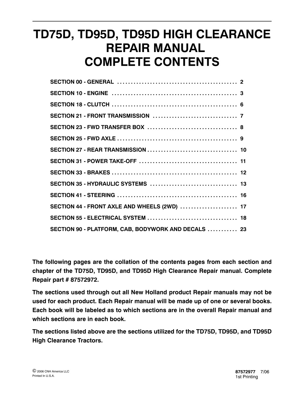
TD75D, TD95D, TD95D HIGH CLEARANCE REPAIR MANUAL COMPLETE CONTENTS SECTION 00 - GENERAL . . . . . . . . . . . . . . . . . . . . . . . . . . . . . . . . . . . . . . . . . . . . 2 SECTION 10 - ENGINE . . . . . . . . . . . . . . . . . . . . . . . . . . . . . . . . . . . . . . . . . . . . . . 3 SECTION 18 - CLUTCH . . . . . . . . . . . . . . . . . . . . . . . . . . . . . . . . . . . . . . . . . . . . . . 6 SECTION 21 - FRONT TRANSMISSION . . . . . . . . . . . . . . . . . . . . . . . . . . . . . . . 7 SECTION 23 - FWD TRANSFER BOX . . . . . . . . . . . . . . . . . . . . . . . . . . . . . . . . . 8 SECTION 25 - FWD AXLE . . . . . . . . . . . . . . . . . . . . . . . . . . . . . . . . . . . . . . . . . . . . 9 SECTION 27 - REAR TRANSMISSION . . . . . . . . . . . . . . . . . . . . . . . . . . . . . . . . . 10 SECTION 31 - POWER TAKE-OFF . . . . . . . . . . . . . . . . . . . . . . . . . . . . . . . . . . . . 11 SECTION 33 - BRAKES . . . . . . . . . . . . . . . . . . . . . . . . . . . . . . . . . . . . . . . . . . . . . . 12 SECTION 35 - HYDRAULIC SYSTEMS . . . . . . . . . . . . . . . . . . . . . . . . . . . . . . . . 13 SECTION 41 - STEERING . . . . . . . . . . . . . . . . . . . . . . . . . . . . . . . . . . . . . . . . . . . . 16 SECTION 44 - FRONT AXLE AND WHEELS (2WD) . . . . . . . . . . . . . . . . . . . . . 17 SECTION 55 - ELECTRICAL SYSTEM . . . . . . . . . . . . . . . . . . . . . . . . . . . . . . . . . 18 SECTION 90 - PLATFORM, CAB, BODYWORK AND DECALS . . . . . . . . . . . 23 The following pages are the collation of the contents pages from each section and chapter of the TD75D, TD95D, and TD95D High Clearance Repair manual. Complete Repair part # 87572972. The sections used through out all New Holland product Repair manuals may not be used for each product. Each Repair manual will be made up of one or several books. Each book will be labeled as to which sections are in the overall Repair manual and which sections are in each book. The sections listed above are the sections utilized for the TD75D, TD95D, and TD95D High Clearance Tractors. 2006 CNH America LLC Printed In U.S.A. 87572977 1st Printing 7/06
SECTION 00 - - GENERAL - - CHAPTER 1 1 SECTION 00 - GENERAL Chapter 1 - General CONTENTS Section Description Page General Instructions . . . . . . . . . . . . . . . . . . . . . . . . . . . . . . . . . . . . . . . . . . . . . . . . . . . . . . . . . . . . 3 Health and Safety . . . . . . . . . . . . . . . . . . . . . . . . . . . . . . . . . . . . . . . . . . . . . . . . . . . . . . . . . . . . . . 5 Precautionary Statements . . . . . . . . . . . . . . . . . . . . . . . . . . . . . . . . . . . . . . . . . . . . . . . . . . . . . 15 Safety . . . . . . . . . . . . . . . . . . . . . . . . . . . . . . . . . . . . . . . . . . . . . . . . . . . . . . . . . . . . . . . . . . . . . . 16 Ecology and the Environment . . . . . . . . . . . . . . . . . . . . . . . . . . . . . . . . . . . . . . . . . . . . . . . . . . 19 Minimum Hardware Tightening Torques . . . . . . . . . . . . . . . . . . . . . . . . . . . . . . . . . . . . . . . . . 20 Federal Emissions Warranty . . . . . . . . . . . . . . . . . . . . . . . . . . . . . . . . . . . . . . . . . . . . . . . . . . . 22 California Emission Control Warranty Statement . . . . . . . . . . . . . . . . . . . . . . . . . . . . . . . . . . 23 Consumables . . . . . . . . . . . . . . . . . . . . . . . . . . . . . . . . . . . . . . . . . . . . . . . . . . . . . . . . . . . . . . . . 25
SECTION 00 - - GENERAL - - CHAPTER 1 16 SAFETY PRECAUTIONARY STATEMENTS A careful operator is the best operator. Most accidents can be avoided by observing certain precautions. To help prevent accidents, read the following precautions before operating this equipment. Equipment should be operated only by those who are responsible and instructed to do so. Carefullyreviewtheproceduresgiveninthismanualwithalloperators.Itisimportantthatalloperatorsbefamiliar with and follow safety precautions. THE TRACTOR on public roads. Brake both wheels simulta- neously when making an emergency stop. 1. Read the Operator s Manual carefully before using the tractor. Lack of operating knowledge can lead to accidents. 5. Use extreme caution and avoid hard application of the tractor brakes when towing heavy loads at road speeds. 2. Onlyallowproperlytrainedandqualifiedpersons to operate the tractor. 6. Any towed vehicle whose total weight exceeds that of the towing tractor must be equipped with brakes for safe operation. 3. Topreventfalls,usethehandrailsandstepplates when getting on and off the tractor. Keep steps and platform clear of mud and debris. 7. Never apply the differential lock when turning. When engaged, the differential lock will prevent the tractor from turning. 4. Do not permit anyone but the operator to ride on the tractor unless a passenger seat is fitted. There is no safe place for extra riders otherwise. 8. Always check overhead clearance, specifically when transporting the tractor. Watch where you are going, especially obstacles. 5. Replace all missing, illegible or damaged safety decals. at low overhanging 6. Keep safety decals free of dirt or grime. 9. Use extreme caution when operating on steep slopes. 7. Do not modify or alter or permit anyone else to modify or alter the tractor or any of its components or any tractor function without first consulting your dealer. 10. Toavoidoverturns,drivethetractorwithcareand at speeds compatible with safety, especially when operating over rough ground, when crossing ditches or slopes and when turning. 8. Tractor wheels are very heavy. Handle with care and ensure, when stored, that they cannot fall. 11. Ifthetractorbecomesstuckorthetiresarefrozen to the ground, reverse the tractor out to prevent corners. DRIVING THE TRACTOR 1. Always sit in the drivers seat while starting or driving the tractor. 12. Keep the tractor in the same gear when going downhill as would be used when going uphill. Do not coast or freewheel down hills. 2. When driving on public roads, have considera- tion for other road users. Pull off the road occasionallytoallowany followingtraffic topass. Do not exceed the legal speed limit set in your area. OPERATING THE TRACTOR 1. Applytheparkingbrake,placethePTOcontrolin the OFF position, the lift control lever in the down position, the remote control valve levers in the neutral position and the transmission lever in neutral before starting the tractor. 3. Use low beam lights when meeting a vehicle at night. Make sure the lights are adjusted to prevent blinding the driver of an oncoming vehicle 2. Do not start the engine or operate controls while standing beside the tractor. Always sit in the tractorseatwhenstartingtheengineoroperating the controls. 4. Reduce speed before turning or applying the brakes.Ensurethatbothbrakepedalsarelocked together when traveling at road speeds or when
https://www.ebooklibonline.com Hello dear friend! Thank you very much for reading. Enter the link into your browser. The full manual is available for immediate download. https://www.ebooklibonline.com
SECTION 00 - - GENERAL - - CHAPTER 1 17 a hazard both to the operator and to bystanders. Do not overload or operate with attached equipment which is unsafe, not designed for the particular task or is poorly maintained. 3. Donotbypasstheneutralstartswitches.Consult your authorized dealer if your neutral start controlsmalfunction.Usejumpcablesonly inthe recommended manner. Improper use can result in a tractor runaway. 19. The tractor is designed to provide the minimum noise level at the operator s ears and meets or exceeds applicable standards in this respect. However, noise (sound pressure level) in the workplace can exceed 86 dB(A) when working between buildings or in Therefore, it is recommended that operators wear suitable ear protectors during vehicle operation. 4. Avoidaccidentalcontactwiththegearshiftlevers while the engine is running. Unexpected tractor movement can result from such contact. 5. Do not get off the tractor while it is in motion. confined spaces. 6. Shut off the engine and PTO and apply the parking brake before getting off the tractor. 7. Do not park the tractor on a steep incline. OPERATING THE PTO 8. Do not run the tractor engine in an enclosed building without adequate ventilation. Exhaust fumes are toxic and can cause death. 1. When operating PTO driven equipment, shut off the engine and wait until the PTO stops before getting off the tractor and disconnecting the equipment. 9. Always wear a protective mask when working with toxic spray chemicals. Follow the directions on the chemical container. 2. Do not wear loose clothing when operating the power take-off or especially when near rotating equipment. 10. Ifthepowersteeringorengineceasesoperating, stop the tractor immediately as the tractor will be more difficult to control. 3. When operating stationary PTO driven equip- ment, always apply the tractor parking brake and block the rear wheels front and back. 11. Stop the engine and relieve pressure before connecting or disconnecting hydraulic, steering or fuel lines. 4. To avoid injury, do not clean, adjust, unclog or service PTO driven equipment when the tractor engine is running. 12. Tighten all connections before starting the engine or pressurizing lines. 5. Make sure the PTO guard is in position at all times and always replace the PTO cap when the PTO is not in use. 13. Pull only from the swinging drawbar or the lower link drawbar in the lowered position . Use only a drawbar pin that locks in place. Pulling from the tractor rear axle or any point above the axle may cause the tractor to overturn. SERVICING THE TRACTOR 1. The cooling system operates under pressure which is controlled by the radiator cap. It is dangerous to remove the cap whilethe systemis hot. Always turn the cap slowly to the first stop and allow the pressure to escape before removing the cap entirely. 14. If the front end of the tractor tends to rise when heavy implements are attached to the three- point hitch, install front end or front wheel weights. Do not operate the tractor with a light front end. 15. Always select Position Control when attaching implements and when transporting equipment. Be sure hydraulic couplers are properly installed and will disconnect safely in case of accidental detachment of the implement. 2. Do not smoke while refueling the tractor. Keep any type of open flame away. Wait for the engine to cool before refueling. 3. Keep the tractor and equipment, particularly brakes and steering, maintained in a reliable and satisfactory condition to ensure your safety and comply with legal requirements. 16. Do not leave equipment in the raised position when the vehicle is stopped or unattended. 17. Ensure any attached equipment or accessories are correctly installed, are approved for use with the tractor, do not overload the tractor and are operated and maintained in accordance with the instructions issued accessory manufacturer. 4. To prevent fire or explosion, keep open flames away from battery or cold weather starting aids. To prevent sparks which could cause explosion, use jumper cables according to instructions. by the equipment or 5. Stop the engine before performing any service on the tractor. 18. Remember that your tractor, if abused or incorrectly used, can be dangerous and become
SECTION 00 - - GENERAL - - CHAPTER 1 18 6. Escaping diesel/hydraulic fluid under pressure can penetrate the skin causing serious injury. 5. Do not fillthe fueltank to capacity. Allow room for expansion. Donotuseyourhandtocheckforleaks.Use a piece of cardboard or paper to search for leaks. Stop the engine and relieve pressure before connecting or disconnecting lines. Tighten all connections before starting the engine. If fluid is injected into the skin obtain medical attention immediately. 7. Do not modify or alter or permit anyone else to modify or alter the tractor or any of its components or any tractor function without first consulting an authorized dealer. 6. Wipe up spilled fuel immediately. 7. Always tighten the fuel tank cap securely. 8. If the original fuel tank cap is lost, replace it with an approved cap. A non-approved cap may not be safe. 9. Keep equipment clean and properly maintained. 10. Do not drive equipment near open fires. 11. Never use fuel for cleaning purposes. 12. Arrange fuel purchases so that summer grade fuels are not used in the winter. ROPS The tractor may be equipped with a safety frame (ROPS) which must be maintained in a serviceable condition. Be careful when driving through doorways or working in confined spaces with low headroom. 8. The fuel oil in the injection system is under high pressure and can penetrate the skin. Unqualified persons should not remove or attempt to adjust a pump, injector, nozzle or any other part of the injection system. Failure instructions can result in serious injury. to follow these 1. Donotmodify,drill,weldoralter theROPS inany way. 9. Continuous long term contact with used engine oil my cause skin cancer. Avoid prolonged contact with used engine oil. Wash skin promptly with soap and water. 2. Never attempt to straighten or weld the ROPS or retainingbrackets,whichhavesuffereddamage. By doing so you may weaken the structure and endanger your safety. DIESEL FUEL 3. Do not secure any parts on the ROPS or attach it with other than the special high tension bolts and nuts specified. 1. Under alcohol or blended fuels be added to diesel fuel. Thesecombinationscancreatean increasedfire or explosive hazard. In a closed container such as a fuel tank these blends are more explosive than pure gasoline. Do not use these blends. no circumstances should gasoline, 4. Never attach chains or ropes to the safety frame or roll bar for pulling purposes. 5. Never take unnecessary risks even though your safety frame or roll bar affords you the maximum protection possible. 2. Never remove the fuel cap or refuel with the engine running or hot. 3. Do not smoke while refueling the tractor or when standing near fuel. Keep any type of open flame away.Waitfortheenginetocoolbeforerefueling. 6. Whenever possible, operate with the ROPS inits fully upright and locked position. 4. Maintaincontrolofthefuelfilterpipenozzlewhen filling the tank.
SECTION 10 - - ENGINE - - CHAPTER 1 1 SECTION 10 - - ENGINE Chapter 1 - - Engine CONTENTS Section Description Page Specifications . . . . . . . . . . . . . . . . . . . . . . . . . . . . . . . . . . . . . . . . . . . . . . . . . . . . . . . . . . . . . . . . . . 2 Special Tools . . . . . . . . . . . . . . . . . . . . . . . . . . . . . . . . . . . . . . . . . . . . . . . . . . . . . . . . . . . . . . . . 10 Tightening Torques . . . . . . . . . . . . . . . . . . . . . . . . . . . . . . . . . . . . . . . . . . . . . . . . . . . . . . . . . . . 14 Sectional Views . . . . . . . . . . . . . . . . . . . . . . . . . . . . . . . . . . . . . . . . . . . . . . . . . . . . . . . . . . . . . . 15 Troubleshooting . . . . . . . . . . . . . . . . . . . . . . . . . . . . . . . . . . . . . . . . . . . . . . . . . . . . . . . . . . . . . . 17 Overhaul . . . . . . . . . . . . . . . . . . . . . . . . . . . . . . . . . . . . . . . . . . . . . . . . . . . . . . . . . . . . . . . . . . . . 21 10 001 10 Engine . . . . . . . . . . . . . . . . . . . . . . . . . . . . . . . . . . . . . . . . . . . . . . . . . . . . . . . . . . . . . . . . . . 21 Removal . . . . . . . . . . . . . . . . . . . . . . . . . . . . . . . . . . . . . . . . . . . . . . . . . . . . . . . . . . . . . 21 10 001 54 Installation . . . . . . . . . . . . . . . . . . . . . . . . . . . . . . . . . . . . . . . . . . . . . . . . . . . . . . . . . . . . 33 Disassembly . . . . . . . . . . . . . . . . . . . . . . . . . . . . . . . . . . . . . . . . . . . . . . . . . . . . . . . . . . 35 Assembly . . . . . . . . . . . . . . . . . . . . . . . . . . . . . . . . . . . . . . . . . . . . . . . . . . . . . . . . . . . . 50 Compression Test . . . . . . . . . . . . . . . . . . . . . . . . . . . . . . . . . . . . . . . . . . . . . . . . . . . . . 60 Checks, Dimensions, and Repairs . . . . . . . . . . . . . . . . . . . . . . . . . . . . . . . . . . . . . . . . . . . 61 Cylinder Block . . . . . . . . . . . . . . . . . . . . . . . . . . . . . . . . . . . . . . . . . . . . . . . . . . . . . . . . 61 Crankshaft, Main Bearings, and Flywheel . . . . . . . . . . . . . . . . . . . . . . . . . . . . . . . . . 63 Connecting Rods . . . . . . . . . . . . . . . . . . . . . . . . . . . . . . . . . . . . . . . . . . . . . . . . . . . . . . 67 Pistons . . . . . . . . . . . . . . . . . . . . . . . . . . . . . . . . . . . . . . . . . . . . . . . . . . . . . . . . . . . . . . . 68 Valves . . . . . . . . . . . . . . . . . . . . . . . . . . . . . . . . . . . . . . . . . . . . . . . . . . . . . . . . . . . . . . . 71 Tappets . . . . . . . . . . . . . . . . . . . . . . . . . . . . . . . . . . . . . . . . . . . . . . . . . . . . . . . . . . . . . . 71 Camshaft . . . . . . . . . . . . . . . . . . . . . . . . . . . . . . . . . . . . . . . . . . . . . . . . . . . . . . . . . . . . . 72 Valve Timing Check . . . . . . . . . . . . . . . . . . . . . . . . . . . . . . . . . . . . . . . . . . . . . . . . . . . . 73 Cylinder Head . . . . . . . . . . . . . . . . . . . . . . . . . . . . . . . . . . . . . . . . . . . . . . . . . . . . . . . . 74 10 102 70 Rotating Counterweight Dynamic Balancer . . . . . . . . . . . . . . . . . . . . . . . . . . . . . . . . 75 Valve Guides . . . . . . . . . . . . . . . . . . . . . . . . . . . . . . . . . . . . . . . . . . . . . . . . . . . . . . . . . 76 Valve Seats in Cylinder Head . . . . . . . . . . . . . . . . . . . . . . . . . . . . . . . . . . . . . . . . . . . 79 Crankshaft Front Oil Seal . . . . . . . . . . . . . . . . . . . . . . . . . . . . . . . . . . . . . . . . . . . . . . . 80 Valve Clearance . . . . . . . . . . . . . . . . . . . . . . . . . . . . . . . . . . . . . . . . . . . . . . . . . . . . . . . 86
SECTION 10 - - ENGINE - - CHAPTER 1 2 SPECIFICATIONS Engine Type: -- Models TD75D . . . . . . . . . . . . . . . . . . . . . . . . . . . . . . . . . . . . . . . . . . . . . . . . . . . 8045.05R.939 -- Models TD95D . . . . . . . . . . . . . . . . . . . . . . . . . . . . . . . . . . . . . . . . . . . . . . . . . . . 8045.25L.939 Cycle . . . . . . . . . . . . . . . . . . . . . . . . . . . . . . . . . . . . . . . . . . . . . . . . . . . . . . . . . . . . . . . diesel, 4-stroke Fuel injection . . . . . . . . . . . . . . . . . . . . . . . . . . . . . . . . . . . . . . . . . . . . . . . . . . . . . . . . direct Number of cylinders in line . . . . . . . . . . . . . . . . . . . . . . . . . . . . . . . . . . . . . . . . . . . . . 4 Piston diameter -- Models TD75D . . . . . . . . . . . . . . . . . . . . . . . . . . . . . . . . . . . . . . . . . . . . . . . . . . . 104 mm (4.0944 in.) -- Models TD95D . . . . . . . . . . . . . . . . . . . . . . . . . . . . . . . . . . . . . . . . . . . . . . . . . . . 104 mm (4.0944 in.) Piston stroke . . . . . . . . . . . . . . . . . . . . . . . . . . . . . . . . . . . . . . . . . . . . . . . . . . . . . . . . . 115 mm (4.5275 in.) Total displacement: 3908 cm3(238 cu. in.) 3908 cm3(238 cu. in.) 2450 to 2500 rpm -- Models TD75D . . . . . . . . . . . . . . . . . . . . . . . . . . . . . . . . . . . . . . . . . . . . . . . . . . . -- High idle speed . . . . . . . . . . . . . . . . . . . . . . . . . . . . . . . . . . . . . . . . . . . . . . . . . . . . . . Models TD95D . . . . . . . . . . . . . . . . . . . . . . . . . . . . . . . . . . . . . . . . . . . . . . . . . . . Low idle speed . . . . . . . . . . . . . . . . . . . . . . . . . . . . . . . . . . . . . . . . . . . . . . . . . . . . . . . 625 to 675 rpm Compression ratio Model TD75D . . . . . . . . . . . . . . . . . . . . . . . . . . . . . . . . . . . . . . . 17:1 naturally aspirated Compression ratio for Model TD95D . . . . . . . . . . . . . . . . . . . . . . . . . . . . . . . . . . . . 16.5:1 turbocharged Maximum power: -- Models TD75D . . . . . . . . . . . . . . . . . . . . . . . . . . . . . . . . . . . . . . . . . . . . . . . . . . . gross 58.8 kW (80 hp) -- Models TD95D . . . . . . . . . . . . . . . . . . . . . . . . . . . . . . . . . . . . . . . . . . . . . . . . . . . gross 69.1 kW ( 94 hp) Maximum power speed . . . . . . . . . . . . . . . . . . . . . . . . . . . . . . . . . . . . . . . . . . . . . . . . 2300 rpm Maximum engine torque for Models TD75D @ 1400 rpm . . . . . . . . . . . . . . . . . . . 282 N m (208 lb-ft) Maximum engine torque for Models TD95D @ 1400 rpm . . . . . . . . . . . . . . . . . . . 365 N m (269 lb-ft) Number of main bearings . . . . . . . . . . . . . . . . . . . . . . . . . . . . . . . . . . . . . . . . . . . . . . 5 Sump pan . . . . . . . . . . . . . . . . . . . . . . . . . . . . . . . . . . . . . . . . . . . . . . . . . . . . . . . . . . . structural, cast iron Rev counter/hourmeter . . . . . . . . . . . . . . . . . . . . . . . . . . . . . . . . incorporated in control panel Operating system . . . . . . . . . . . . . . . . . . . . . . . . . . . . . . . . . . . . . . . from gear on camshaft Hour counter calibrated for engine speed of . . . . . . . . . . . . . . . . 1800 rpm (continued)
SECTION 10 - - ENGINE - - CHAPTER 1 21 OVERHAUL ENGINE Removal DANGER Lift and handle all heavy parts using suitable lifting equipment. Make sure that the load is supported by means of suitable slings and hooks. Makesurethatno-oneisstandinginthevicinityofthe load to be lifted. CAUTION Always use suitable tools to align holes in parts. NEVER USE YOUR FINGERS OR HANDS. 1. Drain oil from the transmission/gearbox. 2. Drain the cooling system. 1 25621 9 3. Unscrew the nut (1) from the front ballast retaining pin. 1 1 TRE0601A 10
SECTION 10 - - ENGINE - - CHAPTER 1 22 Remove the ballast (1) from the front support. 4. 1 1 TRE0602A 11 5. Removetheexhaustpipe.Attachliftingchainsto the hood (1) using tools 50131 and 50132 and attach the chain to the hoist. 1 24872 12 6. Detach headlamps (2). the electrical leads (1) from the 1 2 24873 13 7. Detach the struts (1) from hood. 1 1 TRE0603A 14
SECTION 10 - - ENGINE - - CHAPTER 1 23 8. Remove the four hood hinge bolts (1) and lift the hood clear. 1 1 TRE0604A 15 9. Removethefanguard(1)fromright-hand sideof the fan. 1 25028 16 10. Disconnectthetachometercable(1)andremove the retaining ring and sleeve. 1 25046 17 11. Detach the throttle controlspring (1) and remove the throttle lever (2). 1 1 2 2 25183 18 25183
SECTION 10 - - ENGINE - - CHAPTER 1 24 12. Detach thecabair-conditioningpipes(1) and(2) (if applicable). 1 2 24892 19 13. Detach applicable). the cab heating pipes (1) and (2) (if 1 2 25411 20 14. Disconnect connectors. the main harness electrical 1 TRE0605A 21
SECTION 10 - - ENGINE - - CHAPTER 1 25 15. Remove the fusebox by unscrewing the nut (1) 1 TRE0606A 22 16. Disconnectthedeliveryandreturnlines(1)tothe power steering cylinders. 1 TRE0607A 23 17. Remove the supply hose (1) from the lift pump. 1 TRE0608A 24
SECTION 10 - - ENGINE - - CHAPTER 1 26 18. Detach the lift pump delivery pipe (1). 1 TRE0609A 25 19. Detach the fuel pumpandthepipeconnectingthefueltanktothe fuel filter (1). pipes from the fuel injection 1 TRE0610A 26 20. Remove the fuel filter (1) and support. 1 25035 27
SECTION 10 - - ENGINE - - CHAPTER 1 27 21. Remove the front, center and rear retaining bolts from the front axle drive shaft guard and remove the guard (models with FWD). 25038 28 22. Remove the circlip (2) from the front of the drive shaft and slide the sleeve (1), in the direction shown by the arrow (see figure), until it is free of the splines on the front axle (models with FWD). 2 1 25039 29 23. Remove the circlip (2) from the rear of the drive shaft and slide the sleeve (1), in the direction shown by the arrow (see figure), until it is free of the spines on the drive shaft (models with FWD). 1 2 25040 30 24. Remove the retainingbolts fromthe centraldrive shaft support (1) and remove the shaft complete with support (models with FWD). 1 25041 31
SECTION 10 - - ENGINE - - CHAPTER 1 28 25. Withdraw the pin securing the differential lock knob (1), remove the knob and remove the mat from the floor. 1 TRE0611A 32 26. Unscrew the nuts (1) and the bolts securing the engine to the transmission. Access is through the two slots in the cab floor. 1 1 TRE0612A 33 27. Unscrew the four lower bolts (1) securing the engine to the transmission. 1 25049 34
SECTION 10 - - ENGINE - - CHAPTER 1 29 28. Position stand 380000236 underneath the trac- tor and insert a wedge (1), either side of the axle, to prevent the axle from pivoting. 1 25050 35 29. Insert a wooden block between the stands and the tractor. 1 25051 36 30. Place a fixed stand (1) underneath the drawbar support and apply the handbrake. 1 25052 37 32. Unscrew the four remaining bolts securing the engine to the transmission. 33. Separate the engine from the transmission. 1 31. Remove the distance collar (1) between the engine and transmission. 25055 38
Suggest: If the above button click is invalid. Please download this document first, and then click the above link to download the complete manual. Thank you so much for reading
SECTION 10 - - ENGINE - - CHAPTER 1 30 34. Place a fixed stand (1) underneath the front ballast support and chock the wheels with wooden wedges (2). 1 2 25056 39 35. Insert tool 380000292 (1) in the clutch center hole. Unscrew the six bolts (2) securing the clutch to the flywheel and remove complete clutch assembly. 1 2 25057 40 36. Remove the radiator support bracket (1). 1 TRE0613A 41
https://www.ebooklibonline.com Hello dear friend! Thank you very much for reading. Enter the link into your browser. The full manual is available for immediate download. https://www.ebooklibonline.com