JCB VIBROMAX 1103 Single Drum Roller Service Repair Manual Instant Download
Please open the website below to get the complete manualnn//

Download Presentation

Please find below an Image/Link to download the presentation.
The content on the website is provided AS IS for your information and personal use only. It may not be sold, licensed, or shared on other websites without obtaining consent from the author. Download presentation by click this link. If you encounter any issues during the download, it is possible that the publisher has removed the file from their server.
E N D
Presentation Transcript
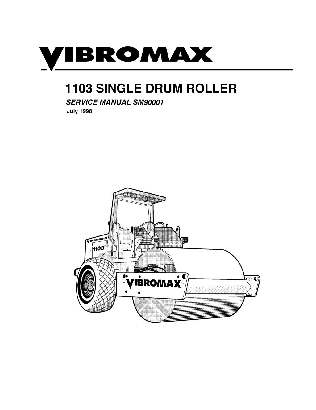
1103 SINGLE DRUM ROLLER SERVICE MANUAL SM90001 July 1998
CALIFORNIA Proposition 65 Warning Diesel engine exhaust and some of its constituents are known to the State of California to cause cancer, birth defects, and other reproductive harm.
TABLE OF CONTENTS SECTION ONE GENERAL INFORMATION MACHINE DESCRIPTION......................................................................... 1 - 3 SERIAL NUMBERS .........................................................................1 - 5 IDENTIFYING MACHINE COMPONENTS ......................................1 - 6 SAFETY, GENERAL.................................................................................. 1 - 7 SPARK ARRESTER ........................................................................1 - 7 SAFETY, PERSONAL................................................................................ 1 - 7 SAFETY, MACHINE OPERATION............................................................. 1 - 8 SAFETY, MAINTENANCE .........................................................................1 - 9 GENERAL INFORMATION ......................................................................1 - 12 CLEANING ....................................................................................1 - 12 INSPECTION .................................................................................1 - 12 BEARINGS ....................................................................................1 - 12 NEEDLE BEARINGS .....................................................................1 - 12 GEARS ..........................................................................................1 - 12 OIL SEALS, O-RINGS, & GASKETS ............................................ 1 - 12 SHAFTS ........................................................................................ 1 - 12 SERVICE PARTS ..........................................................................1 - 12 LUBRICATION ..............................................................................1 - 12 STANDARD TORQUE DATA ...................................................................1 - 13 MACHINE SPECIFICATIONS ..................................................................1 - 15 FLUID SPECIFICATIONS ........................................................................1 - 17 DIESEL FUEL SPECIFICATION...............................................................1 - 18 ENGINE OIL SPECIFICATION................................................................ 1 - 19 TIRE BALLAST ........................................................................................1 - 20 SECTION TWO ENGINE CUMMINS ENGINE WARRANTY ..............................................................2 - 3 ENGINE REMOVAL ...................................................................................2 - 4 SECTION THREE ELECTRICAL GENERAL INFORMATION ........................................................................3 - 2 INSTRUMENT PANEL............................................................................... 3 - 4 UNDERSTANDING ELECTRICAL SCHEMATICS ....................................3 - 7 UNDERSTANDING RELAYS .....................................................................3 - 9 VIBROMAX RELAYS ....................................................................3 - 11 STARTER/CHARGING CIRCUIT (before JKC8302000) .........................3 - 13 STARTER/CHARGING CIRCUIT (AFTER JKC8302000) ........................3 - 15 UNDERSTANDING BATTERIES .............................................................3 - 15 BATTERY DIAGNOSTICS ............................................................3 - 16 July 1998 3
TABLE OF CONTENTS UNDERSTANDING ALTERNATORS ......................................................3 - 17 CHARGING SYSTEM DIAGNOSTICS .........................................3 - 18 VOLTAGE CHECKS AT ALTERNATOR ..................................... 3 - 19 SYSTEM LEAKAGE .....................................................................3 - 19 CIRCUIT WIRING TEST ...............................................................3 - 19 MEASURING ALTERNATOR OUTPUT ....................................... 3 - 20 UNDERSTANDING STARTERS ...................................................3 - 20 STARTER SOLENOID ..................................................................3 - 21 STARTER SYSTEM DIAGNOSTICS ......................................................3 - 21 SOLENOID CIRCUIT TEST ..........................................................3 - 21 STARTER CIRCUIT WIRING TEST .............................................3 - 22 STARTER MOTOR TEST .............................................................3 - 23 INSTRUMENTATION PANEL .................................................................3 - 25 EMERGENCY STOP SWITCH/ BRAKE SWITCH ..................................3 - 27 VIBRATION CIRCUIT ..............................................................................3 - 29 VIBRATION AFTER JKC8300700 ..........................................................3 - 31 LIGHTING CIRCUIT ................................................................................3 - 33 WORK LIGHTS, ACCESSORY PLUG, HEATER AND WIPERS ...........3 - 35 CAB WIRING ...........................................................................................3 - 46 WIRE HARNESS 7250/16315................................................................. 3 - 47 WIRE CHART 7250/16315 ......................................................................3 - 52 WIRE HARNESS 7250/16110................................................................. 3 - 56 WIRE CHART 7250/16110...................................................................... 3 - 59 SECTION FOUR HYDRAULIC PUMP SUCTION LINES ............................................................................4 - 2 HYDRAULIC COOLING SYSTEM............................................................. 4 - 4 HYDRAULIC DRAIN LINES ...................................................................... 4 - 6 HYDRAULIC TEST SYSTEM .................................................................... 4 - 8 HYDRAULIC TEST STATION ...................................................................4 - 9 CHARGE SYSTEM ..................................................................................4 - 11 PROPULSION SYSTEM .........................................................................4 - 13 MULTIFUNCTION VALVES .................................................................... 4 - 17 PROPULSION SYSTEM DIAGNOSTICS................................................ 4 - 18 INTERNAL LEAKAGE ..................................................................4 - 18 PUMP SERVO CONTROL ...................................................................... 4 - 19 VIBRATION SYSTEM ..............................................................................4 - 21 VIBRATION FREQUENCY ......................................................................4 - 23 VIBRATION AMPLITUDE ........................................................................4 - 25 VIBRATORY SYSTEM DIAGNOSTICS ..................................................4 - 26 STEERING SYSTEM............................................................................... 4 - 27 PARKING BRAKE SYSTEM ....................................................................4 - 30 TOWING YOUR MACHINE .......................................................... 4 - 31 PARKING BRAKE DIAGNOSTICS ..........................................................4 - 31 4 July 1998
https://www.ebooklibonline.com Hello dear friend! Thank you very much for reading. Enter the link into your browser. The full manual is available for immediate download. https://www.ebooklibonline.com
TABLE OF CONTENTS DIFFERENTIAL LOCK SYSTEM .............................................................4 - 35 HYDRAULIC SCHEMATIC ......................................................................4 - 38 SECTION FIVE FINAL DRIVES GENERAL INFORMATION ........................................................................5 - 2 OPERATION ..............................................................................................5 - 3 KESSLER AXLE..........................................................................................5 - 4 SPETH STANDARD AXLE ........................................................................ 5 - 5 REAR AXLE REMOVAL .............................................................................5 - 6 AXLE INSTALLATION ................................................................................5 - 7 AXLE TUBE DISASSEMBLY.....................................................................5 - 8 PLANETARY DISSASSEMBLY ...............................................................5 - 10 DIFFERENTIAL LOCK REMOVAL ..........................................................5 - 12 DIFFERENTIAL LOCK ASSEMBLY .........................................................5 - 13 AXLE TUBE AND PLANETARY ASSEMBLY ..........................................5 - 14 INTERMEDIATE GEARBOX DISASSEMBLY .........................................5 - 18 INTERMEDIATE GEARBOX ASSEMBLY ...............................................5 - 20 DIFFERENTIAL DISASSEMBLY .............................................................5 - 22 DIFFERENTIAL ASSEMBLY ................................................................... 5 - 24 DRUM REMOVAL ....................................................................................5 - 29 DRUM INSTALLATION ............................................................................5 - 29 DRUM DRIVE ...........................................................................................5 - 30 DRUM DRIVE BEARING REMOVAL....................................................... 5 - 34 DRUM DRIVE BEARING INSTALLATION ...............................................5 - 36 DRUM DRIVE MOTOR REPAIRS ...........................................................5 - 36 SECTION SIX PARKING BRAKE SYSTEM DESCRIPTION ...........................................................................................6 - 2 RELEASE AND TOWING ..........................................................................6 - 4 DRUM MOTOR BRAKE .............................................................................6 - 5 DISASSEMBLY OF MOTOR BRAKE.............................................. 6 - 6 ASSEMBLY OF MOTOR BRAKE ....................................................6 - 6 STANDARD AXLE BRAKE........................................................................ 6 - 8 BAND BRAKE ADJUSTMENT................................................................... 6 - 9 BAND BRAKE CYLINDER....................................................................... 6 - 10 HEAVY DUTY AXLE BRAKE ...................................................................6 - 11 July 1998 5
TABLE OF CONTENTS SECTION SEVEN VIBRATION SYSTEM VIBRATION SYSTEM ................................................................................ 7 - 2 VIBRATION FREQUENCY ........................................................................ 7 - 3 VIBRATION AMPLITUDE .......................................................................... 7 - 5 VIBRATORY SYSTEM DIAGNOSTICS .................................................... 7 - 6 LIFTING DEVICE ....................................................................................... 7 - 7 DRUM REMOVAL .....................................................................................7 - 8 DRUM INSTALLATION ............................................................................. 7 - 8 EXCITER BEARING REMOVAL ............................................................... 7 - 9 EXCITER BEARING ASSEMBLY............................................................ 7 - 14 SMOOTH DRUM SHAFT ........................................................................ 7 - 15 PADFOOT DRUM SHAFT .......................................................................7 - 16 SECTION EIGHT STEERING SYSTEM SPECIAL TOOLS ...................................................................................... 8 - 2 ARTICULATION JOINTS ........................................................................... 8 - 3 JOINT DISASSEMBLY.............................................................................. 8 - 5 JOINT ASSEMBLY .................................................................................... 8 - 9 STEERING CYLINDER ........................................................................... 8 - 12 SECTION NINE CHASSIS DRUM FRAME .......................................................................................... 9 - 2 REAR FRAME ........................................................................................... 9 - 3 SIDE FRAME ............................................................................................. 9 - 4 ENGINE COMPARTMENT PANELS......................................................... 9 - 5 OPERATOR PLATFORM .......................................................................... 9 - 6 ROLLOVER PROTECTION STRUCTURE ............................................... 9 - 7 SECTION TEN ATTACHMENTS LEVELING BLADE ..................................................................................10 - 2 BLADE CONTROL ..................................................................................10 - 3 BLADE HYDRAULIC LINES ....................................................................10 - 4 6 July 1998
1 SECTION ONE GENERAL INFORMATION CALIFORNIA Proposition 65 Warning Diesel engine exhaust and some of its constituents are known to the State of California to cause cancer, birth defects, and other reproductive harm. July 1998 1 - 1
SECTION ONE GENERAL INFORMATION MACHINE DESCRIPTION The 1103 Vibratory Roller is the replacement for the 1102. Like the 1102, the 1103 is available in smooth drum or pad foot drum con- figuration. The 1103 how- ever, is also offered with a standard Speth axle or a heavy duty Speth axle for high gradeability applica- tions. The 1103 uses the Cum- mins 5.9 liter 6 cylinder tur- bocharged engine at 130 gross horsepower. Chang- es in the drive pump and the addition of a heavy duty axle drive motor result in improved machine performance. The vibratory drum diameter remains the same and drum width is two inches narrower. The drum s centrifugal force has been increased 22%. A Sauer Sundstrand Series 90 variable displacement, axial piston hydrostatic pump, used for machine propulsion, is mounted to the flywheel end of the engine. It provides oil to a Poclain MS25 drum drive motor and a Sauer Sundstrand 2 speed axle drive motor in a parallel path. The Poclain motor is mounted on the left side of the drum and is isolated from the drum by rubber buffers. The axle drive motor on the standard axle has a displacement of 80 cc while the motor on the heavy duty axle displaces 110cc. The vibration system uses a Sauer Sundstrand Series 90 hydrostatic pump similar to the pro- pulsion pump and mounted directly behind the propulsion pump. The vibratory pump supplies oil to a Sauer Sundstrand hydrostatic motor mounted at the right side of the drum. Like the 1102, the 1103 smooth drum operates at frequencies of 1680 or 2160 vibrations per minute, July 1998 1 - 3
SECTION ONE GENERAL INFORMATION while the pad foot version operates only at the lower frequency. A steering pump, mounted to the rear of the vibration pump, provides the oil needed for steering. The steering pump is also a sec- ond charge pump in the propulsion/vibra- tion circuit. The steering pump draws oil from the reservoir, passes it through the steering control valve, through the inline hy- draulic filter, and into the charge circuit. The charge pump draws oil from reservoir, joins the steering oil at the filter, passes it through the filter and into the charge circuit. The 1103 has brakes at both the front drum and the rear axle. A spring applied-hydrau- lically released multi disc brake is part of the drum drive motor. The standard axle machine uses a spring applied-hydraulical- ly released band brake at the intermediate gearbox while the heavy duty axle incorpo- rates multiple disc brakes at the intermedi- ate gearbox. Pressure testing of the 1103 has been made easier by placing all the test ports at a centrally located test station under the op- erators platform on the right side of the ma- chine. The electrical system of the 1103 consists of a 12 volt battery, starter, alternator sys- tem, optional lighting and standard instru- mentation. 1 - 4 July 1998
SECTION ONE GENERAL INFORMATION SERIAL NUMBERS 1 2 3 4 5 6 7 8 Model / Serial Number Front Drum Drive Motor S/N Steering Unit S/N Axle S/N Vibratory Motor S/N Hydraulic Pumps S/N Axle Drive Motor S/N Engine S/N July 1998 1 - 5
SECTION ONE GENERAL INFORMATION IDENTIFYING MACHINE COMPONENTS 1 Articulation joint 2 Smooth drum 3 4 Operator s stand 5 6 Hydraulic tank 7 8 Planetary gear 9 10 Drum drive motor 11 Isolation buffer 12 13 14 15 16 17 18 19 20 21 22 23 24 Lifting and towing eyes Fuel tank Air filter system Hydraulic oil cooler Roll over protective structure Vibration motor Steering cylinder Hydraulic pumps Parking brake cylinder Intermediate gear box Axle drive motor Radiator Lifting eye Battery Engine Differential Scraper 1 - 6 July 1998
SECTION ONE GENERAL INFORMATION SAFETY, GENERAL The information in this manual does not replace any safety rules and laws used in your area. Before you operate this machine, learn the rules and laws for your area and make sure your machine has the correct equipment according to these rules and regulations. A fire can cause injury or death. Always have a fire extinguisher on the job site near the machine. Make sure the fire extin- guisher is serviced according to the manufacturer s instructions. Your safety and the safety of other persons in the work area are dependent on your correct operation of this machine. Foreign materials and loose objects on the steps, hand rails, and in the operator s compart- ment can cause accidents and injury. Keep the steps, hand rails, and opera- tor s compartment clear at all times. Know the location and function of all machine controls. Clear the area of other persons before you start the engine. Always use the seat belt when operating the machine. Make sure the buckle for the seat is fastened correctly. Check all controls in a safe area before you operate the machine. Understand the limits of the machine. Do not try to do too much too fast. Make sure cab win- dows are clean and unobstructed. Keep the machine under control at all times. Know and under- stand the arrangements for movement of trucks, machines, and persons on your job site. Understand and follow the instructions of flagmen, road signs, or signals. SPARK ARRESTER NOTE: Rules or laws in some areas can make it necessary for this machine to be equipped with a spark arrester or spark arrester muffler. Check the rules or laws in your area. Always wear the SAFETY, PERSONAL proper ear protection when operating this machine. Permanent hearing loss can result from extended exposure to loud noises. Loose clothing and jewelry can cause an accident. Do not wear loose clothing or jewelry that can catch on controls, etc. Do wear safety shoes, hard hat, heavy gloves, etc. when required for your protection. Check machine con- trols for proper operation prior to starting the machine. July 1998 1 - 7
Suggest: If the above button click is invalid. Please download this document first, and then click the above link to download the complete manual. Thank you so much for reading
SECTION ONE GENERAL INFORMATION Holes, obstruc- Look at the instru- tions, debris, and other work area haz- ards can cause injury or death. Always walk around and look for these and other hazards before you operate your machine in a new work area. ments and gauges frequently when you operate. Make sure all systems are in the proper operating range. This machine uses an articulating joint. Keep all persons clear of this pinch area when the engine is running. Machine movement can cause personal injury. Electrical cables, gas pipes, water pipes, sewers, or other underground objects can cause injury or death. Know the location of underground hazards before you operate your machine in a new work area. A machine out of control can cause injury or death. You must make a judgement if weather and earth conditions will permit safe operation on a hill, ramp, or rough ground. Adjust machine operation accordingly. Not doing, or wrong machine inspection and maintenance can cause accidents. Always follow the instructions in this manual for machine inspection and maintenance. Operating your machine in, on, or near a trench, high bank, or overhang is extra dangerous and can cause injury or death. You must make a judgement if your machine can be safely operated near any of these areas. Use wall supports if necessary. SAFETY, MACHINE OPERATION Dust, smoke, fog, etc. can decrease your vision and cause an accident. Always stop or slow the machine until you can see your work area and the surrounding traffic Sparks from the electrical system or engine exhaust can cause a fire or explosion. Before you operate this machine in an area with flammable dust or vapors, use good ventilation to remove the flam- mable dust or vapors. Operate the con- trols from the operator s seat only, and keep your hands on the controls during operation. Engine exhaust Do not permit other fumes can cause injury or death. If you operate this machine in an enclosed area, use good ventilation to replace the exhaust fumes with fresh air. persons to ride on the machine. 1 - 8 July 1998
SECTION ONE GENERAL INFORMATION The vibrations from Operating this this machine can cause the walls of a trench or high bank to collapse. If you must operate this machine close to a trench or high bank, make sure the walls of the trench or bank are braced. If you do not follow these instructions, you can cause personal injury or death to persons working in these areas. machine too close to High Voltage electrical lines can cause injury or death. Follow the guide lines listed below. NOTE: IF THE CLEARANCES IN THE SPECIFICATIONS BELOW ARE LESS THAN THE CLEARANCES GIVEN IN THE RULES AND LAWS OF YOUR AREA, YOU MUST FOLLOW THE RULES AND LAWS OF YOUR AREA! Electrical Safety Rules Minimum Clearance From Cable When Machine is Working Minimum Clearance From Cable When Transporting Machine Cable Voltage 50,000 volts or less 10 feet (3 meters) 4 feet (1.2 meters) 50,000 volts to 345,000 volts 10 feet (3m) plus 1/2 inch (13mm) for every 1000 volts over 50,000 volts 10 feet (3 meters) 345,000 volts to 750,000 volts 10 feet (3m) plus 1/2 inch (13mm) for every 1000 volts over 50,000 volts 16 feet (5 meters) SAFETY, MAINTENANCE Engine fuel is flam- mable and can cause a fire or an explosion. Do not fill the fuel tank or service the fuel system while the machine is running, or near an open flame, welding, burning cigars and cigarettes, etc. Machine movement without an operator can cause injury or death. If you must service this machine with the engine running, have another person help you and fol- low the instructions in the machine manuals. Lock the articulation joint and do not leave the machine when the engine is running. Flammable clean- ing solvents can cause injury or death. Use nonflammable cleaning solvents for cleaning purposes. July 1998 1 - 9
https://www.ebooklibonline.com Hello dear friend! Thank you very much for reading. Enter the link into your browser. The full manual is available for immediate download. https://www.ebooklibonline.com