Caterpillar Cat CB-534D VIBRATORY COMPACTOR (Prefix EAA) Service Repair Manual Instant Download
Please open the website below to get the complete manualnn//

Download Presentation

Please find below an Image/Link to download the presentation.
The content on the website is provided AS IS for your information and personal use only. It may not be sold, licensed, or shared on other websites without obtaining consent from the author. Download presentation by click this link. If you encounter any issues during the download, it is possible that the publisher has removed the file from their server.
E N D
Presentation Transcript
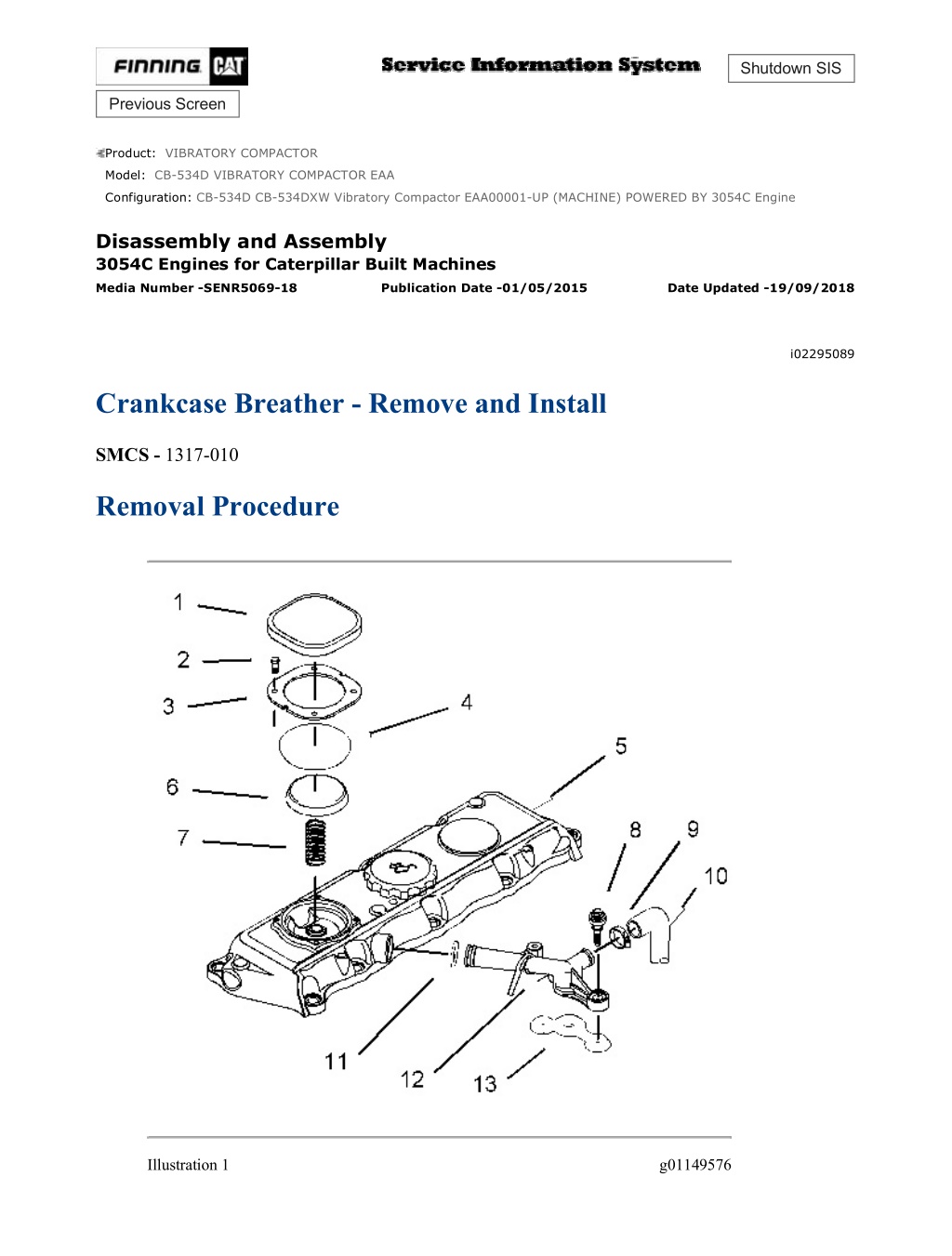
CB-534D CB-534DXW Vibratory Compactor EAA00001-UP (MACHINE) POWERE... 1/3 Shutdown SIS Previous Screen Product: VIBRATORY COMPACTOR Model: CB-534D VIBRATORY COMPACTOR EAA Configuration: CB-534D CB-534DXW Vibratory Compactor EAA00001-UP (MACHINE) POWERED BY 3054C Engine Disassembly and Assembly 3054C Engines for Caterpillar Built Machines Media Number -SENR5069-18 Publication Date -01/05/2015 Date Updated -19/09/2018 i02295089 Crankcase Breather - Remove and Install SMCS - 1317-010 Removal Procedure Illustration 1 g01149576 https://127.0.0.1/sisweb/sisweb/techdoc/techdoc_print_page.jsp?returnurl=/sisw... 2021/5/2
CB-534D CB-534DXW Vibratory Compactor EAA00001-UP (MACHINE) POWERE... 2/3 1. Loosen the clamp (9) and remove the hose (10) from the connector (12). 2. Remove the setscrews (8) and remove the connector (12) from the cylinder head. Remove the gasket (13). Remove the O-ring seal (11) from the connector. Discard the gasket (13) and the O-ring seal (11). 3. Remove the cover (1) from the valve mechanism cover (5). Personal injury can result from parts and/or covers under spring pressure. Spring force will be released when covers are removed. Be prepared to hold spring loaded covers as the bolts are loosened. 4. Remove the screws (2). Remove the plate (3). 5. Remove the diaphragm (4) and the cap (6). Remove the spring (7). Installation Procedure https://127.0.0.1/sisweb/sisweb/techdoc/techdoc_print_page.jsp?returnurl=/sisw... 2021/5/2
CB-534D CB-534DXW Vibratory Compactor EAA00001-UP (MACHINE) POWERE... 3/3 Illustration 2 g01149576 Improper assembly of parts that are spring loaded can cause bodily injury. To prevent possible injury, follow the established assembly procedure and wear protective equipment. 1. Install the spring (7), the cap (6), and the diaphragm (4). 2. Install the plate (3). Install the screws (2). 3. Install the cover (1) on the valve mechanism cover. 4. Install a new O-ring seal (11) on the connector (12). Install a new gasket (13) on the connector (12). Position the connector in the valve mechanism cover. 5. Install the setscrews (8). Tighten the setscrews to a torque of 9 N m (80 lb in). 6. Install the hose (10) on the connector (12). Tighten the clamp (9) to a torque of 5 N m (44 lb in). Copyright 1993 - 2021 Caterpillar Inc. Sun May 2 08:50:55 UTC+0800 2021 All Rights Reserved. Private Network For SIS Licensees. https://127.0.0.1/sisweb/sisweb/techdoc/techdoc_print_page.jsp?returnurl=/sisw... 2021/5/2
https://www.ebooklibonline.com Hello dear friend! Thank you very much for reading. Enter the link into your browser. The full manual is available for immediate download. https://www.ebooklibonline.com
CB-534D CB-534DXW Vibratory Compactor EAA00001-UP (MACHINE) POWERE... 1/4 Shutdown SIS Previous Screen Product: VIBRATORY COMPACTOR Model: CB-534D VIBRATORY COMPACTOR EAA Configuration: CB-534D CB-534DXW Vibratory Compactor EAA00001-UP (MACHINE) POWERED BY 3054C Engine Disassembly and Assembly 3054C Engines for Caterpillar Built Machines Media Number -SENR5069-18 Publication Date -01/05/2015 Date Updated -19/09/2018 i02295100 Valve Mechanism Cover - Remove and Install SMCS - 1107-010 Removal Procedure Start By: a. Remove the heat shields, if equipped. b. Remove the cover for the fuel injection nozzles. Refer to this Disassembly and Assembly Manual, "Fuel Injection Nozzle Cover - Remove and Install". NOTICE Keep all parts clean from contaminants. Contaminants may cause rapid wear and shortened component life. NOTICE Care must be taken to ensure that fluids are contained during performance of inspection, maintenance, testing, adjusting, and repair of the product. Be prepared to collect the fluid with suitable containers before opening any compartment or disassembling any component containing fluids. Refer to Special Publication, NENG2500, "Dealer Service Tool Catalog" for tools and supplies suitable to collect and contain fluids on Cat products. https://127.0.0.1/sisweb/sisweb/techdoc/techdoc_print_page.jsp?returnurl=/sisw... 2021/5/2
CB-534D CB-534DXW Vibratory Compactor EAA00001-UP (MACHINE) POWERE... 2/4 Dispose of all fluids according to local regulations and mandates. Illustration 1 g00951080 1. Remove the breather tube (3) from the valve mechanism cover (1). Refer to this Disassembly and Assembly Manual, "Crankcase Breather - Remove and Install". 2. Remove the fasteners (2). Remove valve mechanism cover (1). Remove the gasket from the cylinder head and discard the gasket. Installation Procedure https://127.0.0.1/sisweb/sisweb/techdoc/techdoc_print_page.jsp?returnurl=/sisw... 2021/5/2
CB-534D CB-534DXW Vibratory Compactor EAA00001-UP (MACHINE) POWERE... 3/4 Illustration 2 g01149828 1. Thoroughly clean the valve mechanism cover (1). Ensure that the groove for the gasket for the valve mechanism cover (1) is clean and dry. Ensure that the mating face on the cylinder head is clean and dry. 2. If the valve mechanism cover (1) is equipped with an oil filler cap, check the condition of the O-ring for the oil filler cap. If necessary, replace the O-ring. 3. Check the condition of the fasteners (2). Replace the fasteners (2), if necessary. 4. Install the gasket and valve mechanism cover (1) on the cylinder head. Illustration 3 g01149832 5. Install the fasteners (2). Tighten the fasteners in the sequence that is shown in Illustration 3to a torque of 9 N m (80 lb in). 6. Connect breather tube (3) to the valve mechanism cover. Refer to this Disassembly and Assembly Manual, "Crankcase Breather - Remove and Install". End By: a. Install the cover for the fuel injection nozzles. Refer to this Disassembly and Assembly Manual, "Fuel Injection Nozzle Cover - Remove and Install". https://127.0.0.1/sisweb/sisweb/techdoc/techdoc_print_page.jsp?returnurl=/sisw... 2021/5/2
CB-534D CB-534DXW Vibratory Compactor EAA00001-UP (MACHINE) POWERE... 4/4 b. If equipped, ensure that the heat shields are clean and free from dust, oil, and paint. Install the heat shields. Copyright 1993 - 2021 Caterpillar Inc. Sun May 2 08:51:51 UTC+0800 2021 All Rights Reserved. Private Network For SIS Licensees. https://127.0.0.1/sisweb/sisweb/techdoc/techdoc_print_page.jsp?returnurl=/sisw... 2021/5/2
CB-534D CB-534DXW Vibratory Compactor EAA00001-UP (MACHINE) POWERE... 1/2 Shutdown SIS Previous Screen Product: VIBRATORY COMPACTOR Model: CB-534D VIBRATORY COMPACTOR EAA Configuration: CB-534D CB-534DXW Vibratory Compactor EAA00001-UP (MACHINE) POWERED BY 3054C Engine Disassembly and Assembly 3054C Engines for Caterpillar Built Machines Media Number -SENR5069-18 Publication Date -01/05/2015 Date Updated -19/09/2018 i02296699 Rocker Shaft and Pushrod - Remove SMCS - 1102-011; 1208-011 Removal Procedure Table 1 Required Tools Tool Part Number Part Description Qty A 6K-0806 Cable Strap 3 Start By: a. Remove the valve mechanism cover. Refer to Disassembly and Assembly, "Valve Mechanism Cover - Remove and Install". NOTICE Keep all parts clean from contaminants. Contaminants may cause rapid wear and shortened component life. https://127.0.0.1/sisweb/sisweb/techdoc/techdoc_print_page.jsp?returnurl=/sisw... 2021/5/2
CB-534D CB-534DXW Vibratory Compactor EAA00001-UP (MACHINE) POWERE... 2/2 Illustration 1 g00960222 Illustration 2 g00960224 1. If the rocker shaft will not be disassembled, install the Tooling (A) around the rocker arms (4) in order to slightly compress the springs (5). The rocker arms must be held away from the machined faces of the cylinder head (2) during installation. 2. Remove the Torx screws (1) from the rocker shaft (3). 3. Remove the rocker shaft assembly from the cylinder head. 4. Remove the pushrods (6) from the cylinder head. Place an identification mark on each of the pushrods for installation. Copyright 1993 - 2021 Caterpillar Inc. Sun May 2 08:52:46 UTC+0800 2021 All Rights Reserved. Private Network For SIS Licensees. https://127.0.0.1/sisweb/sisweb/techdoc/techdoc_print_page.jsp?returnurl=/sisw... 2021/5/2
CB-534D CB-534DXW Vibratory Compactor EAA00001-UP (MACHINE) POWERE... 1/2 Shutdown SIS Previous Screen Product: VIBRATORY COMPACTOR Model: CB-534D VIBRATORY COMPACTOR EAA Configuration: CB-534D CB-534DXW Vibratory Compactor EAA00001-UP (MACHINE) POWERED BY 3054C Engine Disassembly and Assembly 3054C Engines for Caterpillar Built Machines Media Number -SENR5069-18 Publication Date -01/05/2015 Date Updated -19/09/2018 i02298103 Rocker Shaft - Disassemble SMCS - 1102-015 Disassembly Procedure Table 1 Required Tools Tool Part Number Part Description Qty A 1P-1855 Retaining Ring Pliers 1 Start By: a. Remove the rocker shaft assembly. Refer to Disassembly and Assembly, "Rocker Shaft and Pushrod - Remove". Personal injury can result from being struck by parts propelled by a released spring force. Make sure to wear all necessary protective equipment. Follow the recommended procedure and use all recommended tooling to release the spring force. https://127.0.0.1/sisweb/sisweb/techdoc/techdoc_print_page.jsp?returnurl=/sisw... 2021/5/2
CB-534D CB-534DXW Vibratory Compactor EAA00001-UP (MACHINE) POWERE... 2/2 Illustration 1 g01150908 1. Remove the retaining ring (1) and remove the washer (2) from both ends of the rocker shaft assembly. Note: The rocker shaft (7) is not symmetrical as there is a machined flat (6) toward one end of the shaft. 2. Place an identification mark on each of the components for installation. Ensure that you note the component's relationship to the machined flat (6). 3. Remove the rocker arm assembly (3) for the inlet valve from the rocker shaft (7). Remove the rocker arm assembly (4) for the exhaust valve from the rocker shaft (7). 4. Remove the spring (5) from the rocker shaft assembly. 5. Repeat Step 3 and Step 4 in order to completely disassemble the rocker shaft assembly. Copyright 1993 - 2021 Caterpillar Inc. Sun May 2 08:53:42 UTC+0800 2021 All Rights Reserved. Private Network For SIS Licensees. https://127.0.0.1/sisweb/sisweb/techdoc/techdoc_print_page.jsp?returnurl=/sisw... 2021/5/2
CB-534D CB-534DXW Vibratory Compactor EAA00001-UP (MACHINE) POWERE... 1/2 Shutdown SIS Previous Screen Product: VIBRATORY COMPACTOR Model: CB-534D VIBRATORY COMPACTOR EAA Configuration: CB-534D CB-534DXW Vibratory Compactor EAA00001-UP (MACHINE) POWERED BY 3054C Engine Disassembly and Assembly 3054C Engines for Caterpillar Built Machines Media Number -SENR5069-18 Publication Date -01/05/2015 Date Updated -19/09/2018 i02298104 Rocker Shaft - Assemble SMCS - 1102-016 Assembly Procedure Table 1 Required Tools Tool Part Number Part Description Qty A 1P-1855 Retaining Ring Pliers 1 Illustration 1 g01150908 Typical example https://127.0.0.1/sisweb/sisweb/techdoc/techdoc_print_page.jsp?returnurl=/sisw... 2021/5/2
CB-534D CB-534DXW Vibratory Compactor EAA00001-UP (MACHINE) POWERE... 2/2 1. Clean all of the components and inspect all of the components. Inspect the grooves for the circlips (1) and ensure that all of the oil holes in the rocker shaft (7) and in the rocker arms (3 and 4) are not plugged before you begin the assembly procedure. If necessary, replace any worn components and any damaged components. 2. Check the clearance between the rocker shaft (7) and the bushing of every rocker arm (3 and 4). Refer to the Specifications Manual, "Rocker Shaft" or further information. If necessary, replace any worn components. 3. Lubricate all of the components with clean engine oil before assembly. Note: Ensure that the machined flat (6) on the rocker shaft (7) is facing upward. 4. Install a circlip (1) onto the end of the rocker shaft (7) that is closest to the machined flat (6). Install a washer (2) onto the rocker shaft (7). 5. Install the rocker arm assembly (3) for the inlet valve onto the rocker shaft (7). Install the rocker arm assembly (4) for the exhaust valve onto the rocker shaft (7). 6. Install the spring (5) onto the rocker shaft (7). 7. Repeat Step 5 and Step 6 in order to assemble the rocker shaft assembly. Improper assembly of parts that are spring loaded can cause bodily injury. To prevent possible injury, follow the established assembly procedure and wear protective equipment. 8. Install the remaining washer (2) and the remaining circlip (1) onto the rocker shaft (7). Copyright 1993 - 2021 Caterpillar Inc. Sun May 2 08:54:38 UTC+0800 2021 All Rights Reserved. Private Network For SIS Licensees. https://127.0.0.1/sisweb/sisweb/techdoc/techdoc_print_page.jsp?returnurl=/sisw... 2021/5/2
CB-534D CB-534DXW Vibratory Compactor EAA00001-UP (MACHINE) POWERE... 1/3 Shutdown SIS Previous Screen Product: VIBRATORY COMPACTOR Model: CB-534D VIBRATORY COMPACTOR EAA Configuration: CB-534D CB-534DXW Vibratory Compactor EAA00001-UP (MACHINE) POWERED BY 3054C Engine Disassembly and Assembly 3054C Engines for Caterpillar Built Machines Media Number -SENR5069-18 Publication Date -01/05/2015 Date Updated -19/09/2018 i02298106 Rocker Shaft and Pushrod - Install SMCS - 1102-012; 1208-012 Installation Procedure Table 1 Required Tools Tool Part Number Part Description Qty A 6K-0806 Cable Strap 3 NOTICE Keep all parts clean from contaminants. Contaminants may cause rapid wear and shortened component life. https://127.0.0.1/sisweb/sisweb/techdoc/techdoc_print_page.jsp?returnurl=/sisw... 2021/5/2
CB-534D CB-534DXW Vibratory Compactor EAA00001-UP (MACHINE) POWERE... 2/3 Illustration 1 g00960356 Illustration 2 g00960345 1. Apply clean engine lubricating oil to both ends of the pushrods (6). Install the pushrods (6). Note: Ensure that the pushrods are installed in the original location and that the pushrods are seated in the valve lifters correctly. 2. If the rocker shaft was disassembled, install the Tooling (A) around the rocker arms (4) in order to slightly compress spring (5). The rocker arms must be held away from the machined face of the cylinder head (2) during reassembly. 3. Loosen the nut (8) and the adjustment screw (7) on each rocker arm. This will help prevent a bent valve or a bent pushrod during the installation of the rocker shaft. 4. Position the rocker shaft assembly on the cylinder head. Note: The rocker shaft (3) of the rocker shaft assembly is not symmetrical. The rocker shaft (3) has a machined flat at the front end of the shaft. Ensure that the machined flat is toward the top and toward the front end of the engine. 5. Install the Torx screws (1) in the rocker shaft (3). Note: The longest Torx screw must be installed at the front of the cylinder head in the hole (X). 6. Ensure that the adjustment screws (7) are properly seated in the ends of the pushrods (6). 7. Alternately tighten the Torx screws (1). Start from the center and work toward the outside. Tighten the Torx screws (1) to a torque of 35 N m (26 lb ft). 8. Cut and remove the Tooling (A) from the rocker shaft assembly. 9. Adjust the inlet valve lash to 0.20 mm (0.008 inch) and adjust the exhaust valve lash to 0.45 mm (0.018 inch). Refer to Testing and Adjusting, "Engine Valve Lash - Inspect/Adjust" for more information on adjusting the valve lash. End By: https://127.0.0.1/sisweb/sisweb/techdoc/techdoc_print_page.jsp?returnurl=/sisw... 2021/5/2
CB-534D CB-534DXW Vibratory Compactor EAA00001-UP (MACHINE) POWERE... 3/3 a. Install the valve mechanism cover. Refer to Disassembly and Assembly, "Valve Mechanism Cover - Remove and Install". Copyright 1993 - 2021 Caterpillar Inc. Sun May 2 08:55:34 UTC+0800 2021 All Rights Reserved. Private Network For SIS Licensees. https://127.0.0.1/sisweb/sisweb/techdoc/techdoc_print_page.jsp?returnurl=/sisw... 2021/5/2
CB-534D CB-534DXW Vibratory Compactor EAA00001-UP (MACHINE) POWERE... 1/4 Shutdown SIS Previous Screen Product: VIBRATORY COMPACTOR Model: CB-534D VIBRATORY COMPACTOR EAA Configuration: CB-534D CB-534DXW Vibratory Compactor EAA00001-UP (MACHINE) POWERED BY 3054C Engine Disassembly and Assembly 3054C Engines for Caterpillar Built Machines Media Number -SENR5069-18 Publication Date -01/05/2015 Date Updated -19/09/2018 i02298184 Cylinder Head - Remove SMCS - 1100-011 Removal Procedure Start By: a. Drain the coolant from the engine oil cooler into a suitable container for storage or disposal. Drain the engine oil from the engine oil cooler into a suitable container. Refer to Operation and Maintenance Manual for the procedure on draining the engine coolant and the engine oil. b. Remove the hose from the air filter to the integral air inlet. Refer to the OEM information for further details. c. Remove the fuel priming pump. Refer to this Disassembly and Assembly Manual, "Fuel Priming Pump and Fuel Filter Base - Remove and Install". d. Remove the pipe for the boost control. e. Remove the fuel injectors. Refer to this Disassembly and Assembly Manual, "Fuel Injection Nozzles - Remove". f. Remove the exhaust manifold. Refer to Disassembly and Assembly, "Exhaust Manifold - Remove and Install". g. Remove the rocker shaft assembly and the pushrods. Refer to Disassembly and Assembly, "Rocker Shaft and Pushrod - Remove". h. Remove the glow plugs. Refer to this Disassembly and Assembly Manual, "Glow Plugs - Remove and Install". NOTICE https://127.0.0.1/sisweb/sisweb/techdoc/techdoc_print_page.jsp?returnurl=/sisw... 2021/5/2
CB-534D CB-534DXW Vibratory Compactor EAA00001-UP (MACHINE) POWERE... 2/4 Keep all parts clean from contaminants. Contaminants may cause rapid wear and shortened component life. NOTICE Care must be taken to ensure that fluids are contained during performance of inspection, maintenance, testing, adjusting, and repair of the product. Be prepared to collect the fluid with suitable containers before opening any compartment or disassembling any component containing fluids. Refer to Special Publication, NENG2500, "Dealer Service Tool Catalog" for tools and supplies suitable to collect and contain fluids on Cat products. Dispose of all fluids according to local regulations and mandates. Note: Refer to Operation and Maintenance Manual, "Refill Capacities" for the coolant capacity and the engine oil capacity of the engine. Illustration 1 g00951472 1. Remove the setscrew (1) and the fuel line from the cylinder head. 2. Disconnect the harness assembly (4) from the coolant temperature sensor. 3. Disconnect tube assembly (5) from the cylinder head. https://127.0.0.1/sisweb/sisweb/techdoc/techdoc_print_page.jsp?returnurl=/sisw... 2021/5/2
CB-534D CB-534DXW Vibratory Compactor EAA00001-UP (MACHINE) POWERE... 3/4 Illustration 2 g00954953 4. Remove the setscrews (6). Remove the bypass tube (7) from the cylinder head. Remove the O-ring seals from the bypass tube. Discard the O-ring seals. Illustration 3 g00951484 5. Gradually loosen the setscrews (8) in reverse numerical order. Refer to Illustration 3. This will help prevent distortion of the cylinder head. 6. Remove the setscrews (8) from the cylinder head (9). 7. Use a suitable lifting device and carefully lift the cylinder head off the cylinder block. The weight of the cylinder head is approximately 57 kg (126 lb). Note: Take care not to damage the machined surfaces of the cylinder head (9) during removal. https://127.0.0.1/sisweb/sisweb/techdoc/techdoc_print_page.jsp?returnurl=/sisw... 2021/5/2
CB-534D CB-534DXW Vibratory Compactor EAA00001-UP (MACHINE) POWERE... 4/4 Note: Do not use a lever to separate the cylinder head from the cylinder block. NOTICE Place the cylinder head on a surface that will not scratch the face of the cylinder head. 8. Remove the cylinder head gasket. Discard the cylinder head gasket. Note: Note the location of the dowels on the cylinder block. Copyright 1993 - 2021 Caterpillar Inc. Sun May 2 08:56:30 UTC+0800 2021 All Rights Reserved. Private Network For SIS Licensees. https://127.0.0.1/sisweb/sisweb/techdoc/techdoc_print_page.jsp?returnurl=/sisw... 2021/5/2
CB-534D CB-534DXW Vibratory Compactor EAA00001-UP (MACHINE) POWERE... 1/6 Shutdown SIS Previous Screen Product: VIBRATORY COMPACTOR Model: CB-534D VIBRATORY COMPACTOR EAA Configuration: CB-534D CB-534DXW Vibratory Compactor EAA00001-UP (MACHINE) POWERED BY 3054C Engine Disassembly and Assembly 3054C Engines for Caterpillar Built Machines Media Number -SENR5069-18 Publication Date -01/05/2015 Date Updated -19/09/2018 i02298802 Cylinder Head - Install SMCS - 1100-012 Installation Procedure Table 1 Required Tools Tool Part Number Part Description Qty A 9U-6238 Guide Bolt 2 B 8T-3052 Degree Wheel 1 C - Red Rubber Grease - NOTICE Keep all parts clean from contaminants. Contaminants may cause rapid wear and shortened component life. Note: Thoroughly clean the top of the cylinder block and the bottom of the cylinder head. Ensure that there is no debris in the cylinder bores, the coolant passages, and the lubricant passages. Note: Thoroughly clean the hole in the cylinder head for the gas that is ventilated from the crankcase. Ensure that the hole is not restricted by debris and/or oil deposits. https://127.0.0.1/sisweb/sisweb/techdoc/techdoc_print_page.jsp?returnurl=/sisw... 2021/5/2
CB-534D CB-534DXW Vibratory Compactor EAA00001-UP (MACHINE) POWERE... 2/6 Illustration 1 g00951564 1. Install the cylinder head gasket on the dowels (10) on top of the cylinder block. Note: Do not use any sealant or compound on the cylinder head gasket. 2. Install the Tooling (A) in the cylinder block. 3. Use a suitable lifting device to install the cylinder head. The weight of the cylinder head is approximately 57 kg (126 lb). Note: Ensure that the cylinder head is positioned on dowels (10). Take care not to damage the machined surfaces of the cylinder head during installation. 4. Remove the Tooling (A). Illustration 2 g00951563 https://127.0.0.1/sisweb/sisweb/techdoc/techdoc_print_page.jsp?returnurl=/sisw... 2021/5/2
CB-534D CB-534DXW Vibratory Compactor EAA00001-UP (MACHINE) POWERE... 3/6 5. Clean the threads of the setscrews that secure the cylinder head. Inspect the threads of the setscrews that secure the cylinder head. Note: Do not use the setscrews if there is any visual reduction in the diameter of the threads (Y) that has not been engaged with the cylinder block. Use a straight edge to check the bolts. 6. Apply clean engine oil to the threads and the shoulder of the setscrews that secure the cylinder head before installation. Illustration 3 g00951484 7. Install the setscrews (8) in cylinder head (9). Note: The short setscrews are installed in holes that are marked 2, 5, 6, 7, 8, 9, and 10. Note: The long setscrews are installed in holes that are marked 1, 3, and 4. 8. Tighten the setscrews in numerical order to a torque of 50 N m (37 lb ft). Refer to Illustration 3. 9. Tighten the setscrews in numerical order to a torque of 100 N m (74 lb ft). Refer to Illustration 3. https://127.0.0.1/sisweb/sisweb/techdoc/techdoc_print_page.jsp?returnurl=/sisw... 2021/5/2
CB-534D CB-534DXW Vibratory Compactor EAA00001-UP (MACHINE) POWERE... 4/6 Illustration 4 g01151296 10. Use the Tooling (B) to achieve the correct final torque. Note: If the Tooling (B) is not available, place an index mark on each setscrew. 11. Tighten the setscrews in numerical order. Refer to Illustration 3. a. Turn the short setscrews (2, 5, 6, 7, 8, 9, and 10) for an additional 225 degrees. b. Turn the long setscrews (1, 3, and 4) for an additional 270 degrees. Illustration 5 g00954953 12. Install new O-ring seals on the bypass tube (7). Apply Tooling (C) to the O-ring seals. Install the bypass tube in the cylinder head. Install the setscrews (6). https://127.0.0.1/sisweb/sisweb/techdoc/techdoc_print_page.jsp?returnurl=/sisw... 2021/5/2
CB-534D CB-534DXW Vibratory Compactor EAA00001-UP (MACHINE) POWERE... 5/6 Illustration 6 g00951472 13. Connect the tube assembly (5) to the cylinder head. 14. Connect the harness assembly (4) to the coolant temperature sensor. 15. Install bolt (1) and the fuel line to the cylinder head. 16. Fill the cooling system with coolant. Fill the lubrication system with engine oil. Note: Refer to Operation and Maintenance Manual, "Refill Capacities" for the cooling system capacity and the lubrication system capacity of the engine. End By: a. Install the glow plugs. Refer to Disassembly and Assembly Manual, "Glow Plugs - Remove and Install". b. Install the rocker shaft and the pushrods. Refer to Disassembly and Assembly, "Rocker Shaft and Pushrod - Install". c. Install the exhaust manifold. Refer to Disassembly and Assembly, "Exhaust Manifold - Remove and Install". d. Install the fuel injection Nozzles. Refer to Disassembly and Assembly Manual, "Fuel Injection Nozzles - Install". e. Install the pipe for the boost control. f. Install the fuel priming pump. Refer to Disassembly and Assembly Manual, "Fuel Priming Pump and Fuel Filter Base - Remove and Install". g. Install the hose from the integral air inlet to the air filter. Refer to the OEM information for further details. h. Refill the engine with coolant and engine oil. Refer to the Operation and Maintenance Manual for the correct procedure, the quantities, the coolant specification, and the specification for the engine oil. Copyright 1993 - 2021 Caterpillar Inc. Sun May 2 08:57:25 UTC+0800 2021 All Rights Reserved. https://127.0.0.1/sisweb/sisweb/techdoc/techdoc_print_page.jsp?returnurl=/sisw... 2021/5/2
CB-534D CB-534DXW Vibratory Compactor EAA00001-UP (MACHINE) POWERE... 6/6 Private Network For SIS Licensees. https://127.0.0.1/sisweb/sisweb/techdoc/techdoc_print_page.jsp?returnurl=/sisw... 2021/5/2
CB-534D CB-534DXW Vibratory Compactor EAA00001-UP (MACHINE) POWERE... 1/3 Shutdown SIS Previous Screen Product: VIBRATORY COMPACTOR Model: CB-534D VIBRATORY COMPACTOR EAA Configuration: CB-534D CB-534DXW Vibratory Compactor EAA00001-UP (MACHINE) POWERED BY 3054C Engine Disassembly and Assembly 3054C Engines for Caterpillar Built Machines Media Number -SENR5069-18 Publication Date -01/05/2015 Date Updated -19/09/2018 i02333592 Lifter Group - Remove and Install SMCS - 1209-010 Removal Procedure Table 1 Required Tools Tool Part Number Part Description Qty A 1U-7262 Telescoping Magnet 1 Start By: a. Remove the camshaft. Refer to Disassembly and Assembly, "Camshaft - Remove and Install". NOTICE Keep all parts clean from contaminants. Contaminants may cause rapid wear and shortened component life. https://127.0.0.1/sisweb/sisweb/techdoc/techdoc_print_page.jsp?returnurl=/sisw... 2021/5/2
Suggest: If the above button click is invalid. Please download this document first, and then click the above link to download the complete manual. Thank you so much for reading
CB-534D CB-534DXW Vibratory Compactor EAA00001-UP (MACHINE) POWERE... 2/3 Illustration 1 g00540954 1. Use Tooling (A) to remove lifters (1). Note: Place an identification mark on the lifters for installation purposes. Installation Procedure Table 2 Required Tools Tool Part Number Part Description Qty A 1U-7262 Telescoping Magnet 1 NOTICE Keep all parts clean from contaminants. Contaminants may cause rapid wear and shortened component life. 1. Lubricate the lifters with clean oil before installing the lifters in the cylinder block. https://127.0.0.1/sisweb/sisweb/techdoc/techdoc_print_page.jsp?returnurl=/sisw... 2021/5/2
https://www.ebooklibonline.com Hello dear friend! Thank you very much for reading. Enter the link into your browser. The full manual is available for immediate download. https://www.ebooklibonline.com
")
")
")

")
")
")
")
")
")
")
")
")
")
")
")
")
")
")
")
")
")
")
")
")
")
")
")

")