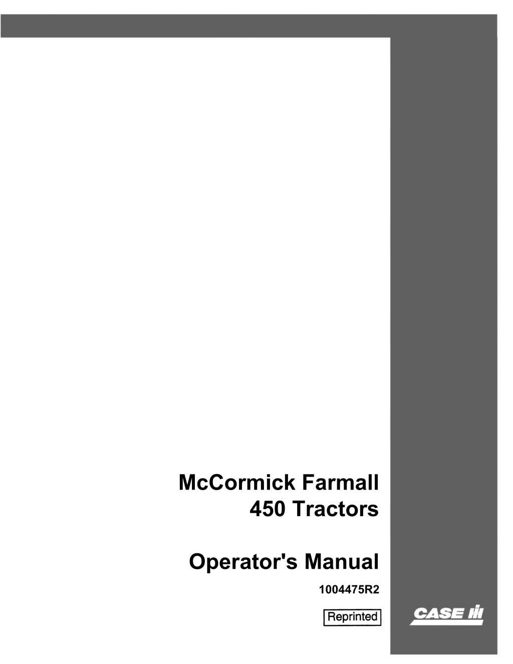
Case IH McCormick Farmall 450 Tractors Operator’s Manual Instant Download (Publication No.1004475R2)
Please open the website below to get the complete manualnn//
Download Presentation

Please find below an Image/Link to download the presentation.
The content on the website is provided AS IS for your information and personal use only. It may not be sold, licensed, or shared on other websites without obtaining consent from the author. Download presentation by click this link. If you encounter any issues during the download, it is possible that the publisher has removed the file from their server.
E N D
Presentation Transcript
McCormick Farmall 450 Tractors Operator's Manual 1004475R2
6 THIS SAFETY ALERT SYMBOL INDICATES IMPORTANT SAFETY MESSAGES IN THIS MANUAL. WHEN YOU SEE THIS SYMBOL, , CAREFULL Y READ THE MESSAGE THAT FOLLOWS AND BE ALERT TO THE POSSIBILITY OF PERSONAL INJURY OR DEA TH. M171B If Safety Decals on this machine use the words Danger, Warning or Caution, which are defined as follows: DANGER: Indicates an immediate hazardous situation which if not avoided, will result in death or serious injury. The color associated with Danger is RED. WARNING: Indicates an potentially hazardous situation which if not avoided, will result in serious injury. The color associated with Warning is ORANGE. CAUTION: Indicates an potentially hazardous situation which if not avoided, may result in minor or moderate injury. It may also be used to alert against unsafe practices. The color associated with Caution is YELLOW. If Safety Decals on this machine are ISO two panel Pictorial, decals are defined as follows: The first panel indicates the nature of the hazard. The second panel indicates the appropriate avoidance of the hazard. Background color is YELLOW."" 6 WARNING IMPROPER OPERATION OF THIS MACHINE CAN CAUSE INJURY OR DEATH. BEFORE USING THIS MACHINE, MAKE CERTAIN THAT EVERY OPERATOR: Prohibition symbols such as \:::I X and 8 if used, are RED. Is instructed in safe and proper use of the machine. Reads and understands the Manual(s) pertaining to the machine. Reads and understands ALL Safety Decals on the machine. Clears the area of other persons. Learns and practices safe use of machine controls in a safe, clear area before operating this machine on a job site. It is your responsibility to observe pertinent laws and regulations and follow Case Corporation instructions on machine operation and maintenance. Bur 0-00000 2001 Case Corporation issued November, 1994 CASE and IH are registered trademarks of Case Corporation
INTERNATIONAl. HARVESTER McCOIMICKe FARMALL@ 450 Tractors
https://www.ebooklibonline.com Hello dear friend! Thank you very much for reading. Enter the link into your browser. The full manual is available for immediate download. https://www.ebooklibonline.com
TO THE OWNER The purpose of this manual is to assist you in realizing the benefits you anticipated when you purchased this International Harvester product. Literally thousands of people have contributed to the design and production of this product and its delivery to you. They have an interest in its successful performance and have prOvided this manual to give you the benefit of the experience they have gained through years of field testing and normal usage of this and similar products. The way you operate and the C<1re you give this product will have much to do with its successful performance. This manual has been carefully prepared and the information arranged and illustrated to make it as easy as possible for you to find the information you wish. It will pay you to read the entire manual carefully before operating and keep it handy for future reference. Your International Harvester Dealer will be glad to answer any further questions you may have on the operation or care of this produd. It is the policy d International Harvester Company to improve its products whenever ii is possible and practical tc do so. We reserve the right to make changes or add improve- ments at any time without incurring any obligation to make such changes on products sold previously. All iH".'",,!ioM one> descriptive;, matter in this publicatian apply to Inlemotional Harvester p f " d u e t ~ sold under the Internalianal, MeCer""',k. McCormick-International, McCormick-Deering, ar McCormi<k-o.,,,rir,g ""etna-;onal trade name.
o Farmall 450 o Farmall 450 Hi-Clear DEALER'S COPY , .. .. '" ; .. .. ~ DELIVERY REPORT (This copy to be filed by dealer.) ,. '" .. Town Tractor being replaced if any: Number tractors owned, including new p Model o AGRICULTURAL 2. Cheek chief source of farm income o COMMERCIAL __ ~ M a k ~ ~ ~ ~ ( Y e a r a ) u r e h a s e , - _ ~ _ ~ Check the Major Use Only for this tractor and complete information under heading: .. Com 0 Wheat 0 0 Orchard 0 Other Truck 0 Cotton 0 Dairy Livestock 0 0 I. T __ ~ __ ~ __ ~ __ ~ __ ~ ______ ~ ____ _ y p e w o r & k ~ ~ ~ 2. List below special duty equipmant to be used: __ ~ __ ~ __ ~ ____________ __ ______ ~ ____ ~ __________ ~ E q u i p m a n t ~ ~ ~ E q w p m a n t ~ ~ Model Model Make Make PREDEL IVERY SERVICE Prior to delivery of the above tractor the following checks and tests were made and corrective action taken as necessary: o ShOfta(e or Damage in Shipment o Extra Equipment and Ac:eessories Cheeked Against Purchase Order o Tire Pressures o Engine Oil Level o Air Cleaner Oil Level o Transmission and Final Drive Oil Levels o Steering Housing Oil Level o IPTO-Rear Unit Oil Level* o Cooling System Level o Torque Cylinder Head-Engine Hot " .. .. o Water Level and Gravity of Battery Cheeked When Installed o Engine Oil Pressure o Cranking Motor o Generator Charging o Lights o T A ~ C l u t e h Linkage" o Engine Clutch o Brakes o {PTO Reactor Bands* o Adjust Valves-Engine Hot o Engine Operation o Gear S h i f t i n g ~ A l l Speeds o Road Test for General Operatinn o Attach Cylind-<)perate Each Hydra. Touch Control Handle. Cheek Reservoir Fluid Level * o Clean and Polish DELIVERY SERVICE At time of delivery the importance of the Operator's Manual was explained and, with it as a guide, instruction was given as indicated by check marks: o Precautions with New Tractor o Lubricating Entire Tractor o Fuel and Lubricant Specifications o Checking Oil Levels o Care of Air Cleaner and Breathers o Servicing Oil Filter o Starting. Stopping. and General Operation o Drawhar AdjUlltmant o ctiees o System o Use of Radiator Shutter" o Care and use of Eleetrall Attachment" o Care and Use of Hydraulic System" Use of Manifold Hcat Control" Care of Fuel System o Adjustment o Adjustment of TA o Care of Ignition System o Care of Generator o Care of Battery o A<ijustmant of IPTO Reactor Bands" Adjustment of Brakes T ~ I n f l a t i o n , We!fhting. Care Wheel Weights and Tread Adjustment o Cold Weather Operation o Storing Tractor o Starting Tractor After Stomp. o Discuss Downhill Operation While Working in TA+ o o ,. * .. .. Fast.Hitch Operation* Clutch tch Linkage" * and Bolts r Clean Whe" So Equipped. The customer's signature below certifies that the tractor was delivered to him in a satisfactory condition and that he received instruction as to its proper operation and maintenance. Appnintmant fol' after-delivery inspection (10 to .30 days after) was made .. ~ .. ..
CUSTOMER'S SERVICE RECORD After-delivery inspection made'-________ _ Oat .. BRIEF DESCRIPTION OF SERVICE PERFORMED RECORD OF CONTACT Symbols- C - Called on T - Telephone L - Letter REMARKS REMARKS REMARKS
o Farmall Farmall 450 450 Hi-Clear DELIVERY REPORT (This copy to be sent to International Harvester District Office.) (EXPORT-5end to Distributor or Affinate General Office.) DISTRICT OFFICE COPY (EXPORT -DISTRIBUTOR OR AFFILIATE OFFICE COPy) Town Tractor being replaced if any: Make.-___ Check the Major Use Only for this tractor and complete information under heading: o AGRICULTURAL !, Acres or hectares in crops'---__ 2. Check chief source of farIr! income o COMMERCIAL I, Type work ______________________ _ Number tractors owned, including new purehase ____ _ As",---(Years) Model D Com D Wheat D Truck D Cotton D Orchard D Other Dairy Livestock D 0 2. List below special duty-equipment to be used: Equipment'-_____________ _ Equipmen .. t ___ , ____________ _ Model Make.- Make PREDELIVERY SERVICE Prior to delivery of the above tractor the following checks and tests were made and corrective action taken as necessary: D Sho!' or Damage in Shipment D Extrs . and Accessories Checked Order D res D Engine Oil Level D Air Cleaner Oil Level D Transmission and Final Drive Oil Levels o Steering Housing Oil Level D IPTO-Rear Unit Oil Level D Cooling System Level D Torque Cylinder Head-Engine Hot D Water Level and Gravity of Battery Checked When Installed D Engine Oil Pressure D Cranking Motor D Generator Charging D Lights D TA-Clutch Linkage* D Engine Clutch D Brakes D IPTO Reactor Bands" D Adjust VaIv_Engine Hot D Engine o Gear o Road Operatinn o Attach Cylinder---Operate Each Hydra-Touch Control Handle. Check Reservoir Fluid Level" o Clean and Polish . DELIVERY SERVICE At time of delivery the importance of the guide, instruction was given as indicated by o Precautions with New Tractor D Lubricating Entire Tractor D Fuel and Lubricant Specifications D Checking Oil Levels D Care of Air Cleaner and Breathers D Servicing Oil Filter D Starting, Stopping. and General Operation D Drawbar Adjustment D Safe Hitch aetices D Care of C System D Uae of Radiator Shutter* D Care and use of EleetraI! Attachment* ator's Manual was explained and, with it as a marks: o Care and Uae of Hydraulic System D F a $ t ~ H i t c h Operation" C Uae of Manifold Heat Control* D Care of Fuel S stem o . Clutch o tch Linkage D Care of Ignition System o Care of Generator D Care of Battery D Adjustment of IPTO Reactor Bands'" D Adjustment of Brakes D Tires-Inflation, Weighting, Care D Wheel Weights and Tread Adjustment D Cold Weather Operation D ring Tractor D . actor After Storage D hill Operation While Working in TA* D T i g h t e n ~ Nuts and Bolts D Keeping Tractor Clean Whe" s.. Equ(pptd. The customer's signature below certifies that the tractor was delivered to him in a satisfactory condition and that he received instruction as to its proper operation and maintenance. Appointment for after-delivery inspection (10 to 30 days after) was made Of ________ ........,,::--__________ Date _
D Farmall 450 Farmall 450 Hi-Clear OWNER'S COPY DELIVERY REPORT (This copy to be retained by owner.) Town Tractor being replaced if any: Number tractors owned, including new purchase ___ _ M a k e ~ ( Y e a r s ) Cheek the Major Use Only for this tractor and complete information under heading-! o AGRICULTURAL I, Acres or hectares in crop"",,, __ ~ 2. Check chief source of farm inCQMe o COMMERCIAL I. Type w o r k ~ ~ ~ ~ ~ ~ ~ ~ ~ ~ ~ ____ ~ Com 0 Wheat 0 Truck 0 Cotto<> 0 0 Orchard 0 Other Dairy LiWlltock 0 0 __ ~ ~ ~ _ 2. List below special duty equipment to be used: E.quipmen""-__ ~ ________________ __________ E . q w p m e n t ~ ~ ~ Maire Modd Model Make PREDELIVERY SERVICE Prior to delivery of the above tractor the following- cheeks and tests were made and corrective action taken as neeessary: o S o Extra Eq . Accessories Checked . Order D I ~ ; " P ; ~ ell 8 Air Cleaner Oil Level o T ransmissinn and Final Drive Oil Levels o Steering Housing Oil Level o I o Cooling System Level o Torque Cylinder H o Water Level and Gravity of Battery Checked When Installed o ~ o Cranking Motor o Generator Charging o Lights o T o Engine Clutch o Brakes o IPTO Reactor Bands" o Adjust Val_Engine Hot o Engine OPeratinn o Gear S h i f ~ A l l Speeds o Rood Test for General Operntinn o Attach C y l Each Hydra-Touch Control Handle. Check Reservoir Auid Level" o Clean and Polish or Damage in Shipment h o r ~ Oil Pressure i n e Oil Levd i n d ~ a t e ~ i n e Linkage" A ~ l u t c h Unit Oil Level'" P T ~ R e a r Hot e a d - ~ i n e DELIVERY SERVICE At time of delivery the importance of the Operator's Manual was explained and, with it as a guide, instruction was given as indicated by cheek marks: o Precautions with New Tractor o Lubricating Entire Tractor o Fuel and Lubrieant Spsoifications o Checking Oil Levels o Care of Air Oeaner and Breathers o Servicing Oil Filter o Starting, Stopping, and General Operation o Drawbar Adjustment o tices o System o Use of Radiator ShuttcJ* o Care and use of Eiectrall Attachment" o Adjustment of Brakes o Tir_In&tion. W e ~ h t i n g . Care o Wheel Weights and Tread Adjustment o Cold Weather Operation o Storing T mctor o Starting Tractor After Storage o Discuss Downhill Operation While Working in T A * o uts and Bolts o torOean Care and Use of Hydraulic System Fast-Hitch Operation'" Use of Manifold Heat Control'" Care of Fuel System Adjustment of Engine Clutch Adjustment of TA Clutch Linkage Care of Ignition System Care of Generator Care of Battery Adjustment of IPTO Reactor Bands" "Wh." So JZqufppeJ. The customer's signature below certifies that the tractor was delivered to him in a satisfactory condition and that he r e e e i ~ e d instruction as to its proper operation and maintenance. Appointment for after.ddivery inspection (10 to 30 clays after) Well made l<U ________ -= __________ _
,q e ~ ( ! J ~ IS THE BEST INSURANCE AGAINST AN ACCIDENT -National Safety Council.
CONTE NTS e_sc_r_ip_t_i_o_n _____________ I ~ a g e N o . ti_o_n _____________ I.P __ ag_e __ N_jo __ II _____________ D __ _____________ D __ e_sc_r_iP __ MAINTENANCE INTRODUCTION Inside Front Cover 2 Delivery report (to be filled in wben { tractor is delivered) .................. . General .......... . .... .............. Serial numbers, engine and tractor ...... . : Adjustable wide tread front axle......... Air cleaning system..................... 47,48 Battery ignition unit. . . . . . . . . . ... . ... . .. 50 to 53 Brakes ........ '" " *' *' '* .. " " ,.. ,.. ,. ,. .............. " " " ~ " .. " " Carburetor. . . . . . . . . . . . . . . . . . . . . . . . . .. 41 to 43 Clutches. . . . . . . . . . . . . . . . . . . . . . . . . . . . . . . Cold weather precautions.. . . . . . . . . . . . . . . Cooling system ......................... 44 to 47 Front wbeels (Farma1l4'O) ............. 69 to 71 Front wheel tread widths (Farmall 450 Hi-Clear) . . . . . . . . . . . . . . . . . . . . . . . . . Fuel strainer. . . . . . . . . . . . . . . . . . . . . . . . . . . 70. 71 2 64" 6:5 ! 66, 67 43. 44 DESCRIPTION Before starting your new tractor ........ , Instruments and controls ... , , . . . . . . . . . . . Preparing your tractor for each day's work Views of the tractor. . . . . . . . . . . . . . . . . . . . 7. 8 4 to 7 9, 10 3 71 41 H y d r a ~ T o u c h system ................... . Independent power t a k e ~ f f ..... ....... i Minor engine service operations .. .. ... f Periodic iospections .................. .. Pneumatic tires ........................ . Rear axle. wide tread .................. Rear wheels ......................... . Spark plugs and cables ................. . Starting and lighting equipment. . . . . . .. 54 to 61 Starting enginesthat ba ve been in storage. Storage battery. . . . . . . . . . . . . . . .. . . . . . . . . Storing and housing your tractor. . . . . . . . Tachometer drive unit. . ................ Trouble shooting. . . . . . . . .. . . . . . . .. .. 80 to 83 Valve clearance adjustment. . ............ 78, 79 68 64 40,41 75 to 78 75 72 to 74 49 OPERATING YOUR TRACTOR Driving the tractor ....... . . . ...... Ground speeds ..... ................. Hitching the tractor to the implement .... Operating a distillate engine on distillate. Operating a distillate engine on gasoline. Operating a gasoline engine ............ . Operating It kerosene engine . .......... Operating the belt pulley ............... . Operating the H y d r a ~ T o u c b system ... .. Operating the pneumatic tire pump ..... . Operating the power take-off ............ . Operating the torque amplifier .......... . 16 to 19 19 21,22 13 to 15 15 11, 12 i 15 20,21 25 to 28 21 23,24 20 84 60, 61 84 62 63 LUBRICATION EXTRA EQUIPMENT AND ACCESSO- RIES ... .......... ,.......... ... . . 85 to 99 General engine lubrication ............. Greasing the front wheels . ... ........ Lubricating oil and grease specifications .. Lubrication guide .... . ........... .. Oil filter ............... ......... . . 29 31 SPECIFICATIONS ....................... 100,101 31,32 32 to 39 30 COMPREHENSIVE INDEX . . ........ 102 to 105 1
INTRODUCTION dons for operating aud mainta101ng the tractor. Disregard the instructions for equipment not on your tractor. When in need of parts. always specify the trac1"or and engine serial numbers. The tractor serial n u m ~ ber is stamped on a name plate attached 1"0 the left side of the dutch housing. See IlluBt. 2",1. Assembled in this book are operating and m a i n t e ~ oance instructions for the FarmaH 450 and 450 Hi-Clear Tractors. This material has been prepared in detail in the hope that it will help you to better understand the correct care and efficient operation of your tractor. If you should need information not given in this manual, or require the services of a trained mechanic, get in touch with the International Harvester dealer in your locality. Dealers are kept informed on the latest methods of servicing tractors. They carry stocks of IH parts, and are backed in every case hy the full facilities of a nearby International Harvester District Office. Throughout this manual the use of the terms LEFT. RIGHT, FRONT, aod REAR must be under- stood to avoid confusion when following i n s t r u c ~ tions. LEFT and RIGHT indicate the left and right sides of the tractor when facing forward in the driver's seat. Reference to FRONT indicates the " radiator end of the tractor; to REAR, the drawbar end. See ll/Hst. 2. IIlusl tA Location of the tractor serial number. The engine serial number is stamped on the right side of the engine crankcase above the crankcase hreather. See Illust. 2B. This serial numher is pre- ceded by the preix C ~ 2 B l > which indicates that it is a carbureted engine with It 281 cnbic-inch piston disp"lacement. Illust. 2 T emu of location. The illustrations in this manual are numbered to correspond with the pages on which they appear; for example, Illusts. 2. 2",1, and 2B aYc an In order to provide a tractor equipped as neady as possible to suit each customer's needs, a variety of extra equipment and accessories is available. Many of these items are illustrated and described in the Extra Equipment and Accessories section of this manual. Where operating and maintaining instruction on these items is required, it is induded in the i n s t r u c ~ 2. IIlusl is Location of ~ e entine serial number. For ready reference. we suggest that you write these serial numbers in the spaces provided on the Delivery Report.
DESCRIPTION lIIust. :3 Left front view of the Farmall 450. must. SA Right front view 01 the Farma!! 450.
DESCRIPTION Instruments and Controls 1I1ust. .. Location o1lMtru_b lind controls. The brake peaallateh (IllNsts. 4 and 18) is used to latch both brake pedals together, causing the brakes to operate simultaneously. Brake Pedals These pedals are used to stop the tractor, to hold the tractor in a stationary position. or to assist in making sharp turns as outlined below: To stop the tractor, depress both pedals at the same time. Before driving the tractor in high gear, always latch the pedals together. To hold the tractor in a stationary position, latch the pedals together. depress them, and lock them in this depressed position by using the hrake pedal lock. To assist in making a pedals individually, depressing the pedal on the side toward which the turn is to be made. Cautionl Always latch the brake pedals together when driving the tractor in high gear (fifth speed). To latch the pedals together, engage the latch (located in hack of the left pedal, Illust. 18) in the slot in back of the right pedal. When the brake pedals are not latched together. the latch should rest in the slot in back of the left brake pedal. The brake pedal lock (Illust, 18) is used to lock the hrake pedals in the depressed position; this prevents the tractor from moving. turn, operate the
DESCRIPTION Lighting Switch Clutch Pedal This pedal, when depressed all the way, d i s ~ engages the engine from the transmission, The switch has three positions: "0" -off posi. tion, "D" -dim lights, and US" -bright lights. Cigarette Lighter Choke Control Button The choke control hutton makes it possible to regulate the carburetor choke from the driver's seat. Pulling o ~ t on the choke control button closes the carburetor choke for starting the engine; pushing it back in opens the choke. Push the lighter in to make electrical contact. Wnen it pops back it is ready for nse. Engine Speed Control Lever ~ Radiator Shutter Control Crank The control crank opens and closes the radiator shutter, controlling the engine temperature. Turn the crank cnunterclockwise to close the shutter and , clockwise to open the shutter. Note: Tractors with gasoline engines are not regularly equipped with this feature. Ignition Switch Illust. 5 A key-type lock ignition switch is located near the left side of the instrument panel and reservoir shroud. Turn the key clockwise to a horizontal posi- tion to turn on the igoition. The key cannot he re- moved when in this position. Various positions of the engine $peed control lever. This lever controls the speed of the engine and, when set in a given position, will maintain a uniform engine speed even though the engine load may vary. The rated or maximum fun load governed speed is 1,450 r.p.m.; maximum idle speed is approximately 1.600 r.p.m.; minimum idle speed (hand throttle) is 400 to 450 r.p.m. with the engine speed control lever fully retarded. See Wltst. 5. Never operate the engine at more than the regular governed speed. Excessive speeds are harmful. Cautionl When the engine is not operating or the engine has stalled and the operator leaves the tractor, the key must be turned to the off position to prevent battery discharge. Electric Starter Button Pushing the button in completes the electrical circuit hetween the battery and the cranking motor solenoid and causes the cranking motor pinion to engage the flywheel ring gear, thereby cranking the engine. Refer to page 14 for starting the engine. Govemor The governor is set at the factory and should require no adjustment. Consult your International Harvester dealer if the governor does not function properly. 5
DESCRIPTION Gearshift Lever ManiFold Heat Control Lever Fourth speed forward Second speed forward Third speed forward....." Fifth speed forward First speed forward lIIust.6A Hut control lever set in the hot po$itlon (distill.te or leerosene englnu only), ~ IIlust.6 This control lever (IIlIIst. 6.1) is used ooly on dis- tillate or keroseoe engines. For normal operation. set the lever io the top notch "H" hot position. If the distillate or kerosene engine is to be operated on gasoline. set the control lever in the bottom notch "e" cold position, and remove the manifold shield. For complete instructions see pages 14 ami 15. Ge.rshlft positions. This lever is used to select the various gear ratios in the traosmission. There are five forward speeds and one reverse speed. See Illnst. 6. Note: The fifth speed is locked out when steel wheels are used; for further instructions see page 19. Charge Indicator This instrument (Illnsts. 4 ami 6B) indicates whether the generator is cbarging or the battery is d i s c b a r g i n ~ . If it shows discharge contlnu- ousIy, investigate the cause to avoid completely dis- charging the battery and pos- sible damage to the genera- tor. See pages 54 to 61 for additional information on electrical equipment. Belt Pulley Control Rod This rod is used to engage or disengage the belt pulley. See pages 20 ami 21 for operating instructions. Power Take-Off Shifter Rod (Transmission-Driven) The shifter rod is used to engage or disengage the power take-<>ff. See page 24 for operating instruc- tions. Independent Power Take-Off Handle The independent power take-off operating handle is used to engage or disengage the independent power take-<>ff. See page 24 for operating instructions. lIIust.68 Cherg. indlmor. Hydra-Touch System Control Handles Thesehaodles (lilnst. 4) operate the Hydra-Touch system. They are used to raise, partially raise or lower direct connected nr trailing-type implements. See page 2' for operating instructions. Torque Amplifier Operating Handle The torque ampllier operating handle is used to engage or disengage the torque amplifier. See page 20 for operating instructions. Heat Indicator This instrument (IIIusts. 4 ami 6C) indicates the relative tempera . the c t e!lgi', le performance. Tbe indicator pointer should be in the center of the "RUN" range (lIbtst. 6C) for engines using distillate or kerosene for fuel, and on the low side of the "RUN" range for en- gines using gasoline for fueL of the system 1IIust. 6C Seat Position Release Lever This lever is used to hold the seat in the desired position. For additional information. see page 16. Hut incllettor in the correct operating position when operating on distillate or kel'ONfle. 6
DESCRIPTION Oil Pressure Gauge This gauge (located on the instrument panel) shows whether lubricating oil is circulating through the engine. The indicator needle should be past the first mark above zero when the engine is running at speeds approx* imately 100 r.p.m. above slow idle speed. See Illust. 7. If the needle does not move past the first mark above zero, stop the engine immediately and investigate the cause of the oil pressure failure. If you are unable to find the cause, consult your International Harvester dealer before operating tbe engine. lIIust. 7 Oil pressure gauge. IIlm.7A Tachometer. which provides a means of setting the exact engine speed specified for power rake-off operations. A mark on the lower haH of the dial indicates a power take-off shaft speed of 537 r.p.m. at 1450 engine r.p.m. Tachometer Refer to the table on page 19 for normal ground speeds according to tire sizes. Refer to "Power Take-Off Specifications" on page 23 for power take-off speeds. This instrument records engine bours of opera- tion, shows normal tractor speeds in miles per hour in all forward gears, and indicates the engine r.p.m. Before Starting Your New Tractor Before starting the engine for the lirst time, remove the spark plugs and put about one teaspoonful of crankcase oil into each cylinder; replace the spark plugs and crank the engine to distribute the oil over the cylinder walls. This assures positive lubrication of the cylinders and pistons immediately after starting and eliminates the possibility of scoring. Lubrication Tractors shipped to destinations in the United States of America, Canada, and Mexico have the crankcase and air deaner filled with SAE-lOW oil from October 15 to April 15, and SAE-20 oil from April 15 to October 15. If the engine is to be operated at tem- peratures for which these oils are recommended (see the "Lubrication Table"), this oil can be used in the engine 150 hours operation. If temperatures are not within the range specified, drain the oil crankcase and air deaner, and replace it with the required amount of fresh oil having the physical properties and proper viscosity suitable for the prevailing temperature and type Lubricate the entire tractor, using the "Lubrica- tion Guide." Check the oil levels of the engine crankcase, air deaner, transmission, belt pulley housing, and aU gear cases to see that they are fmed to the correct levels with oil of the proper viscosity for the p r e v a n ~ ing temperatttte. See the "Lubrication Guide" and the specifications ollubdcants on pages 31 atui j2. service. Tractors pad(ed for export have aU oil drained from the engine crankcase, air cleaner and aU gear cases. 1
DESCRIPTION Fuels having a lower than 83 octane rating can be used satisfactorily in distillate burning engines. These engines are designed for use with fuels having a 40 minimum nctane rating. Fuels having a less than 40 octane rating should be used in kerosene burning engines. See the chart below fnr fuel octane ratings r ~ quired tn obtain the best engine performance and maximum engine life for your type of engine. Pneumatic: Tires Before moving the tractor, check the air pressure in the pneumatic tires and inllate or de1late the front and rear tires to the correct operating pressures. See the table on page 76. Rear Wheels Before operating the tractor. check the rear wheel hub damp bolts to make certain that they are torqued to 390-440 ft. Ibs. Tighten the rear wheel hub clamp bolts a l t e r n a t e ~ ly and a little at a time to prevent excessive tension at any location. Type of Engine Fuel OCtl!.ne Gasoline burning 83 and up Distillate burning 40 to 83 Steel Wheels If your tractor is equipped with steel wheels, or has new wheel and lug installations. it is advisable to check and tighten the rear wheel bolts at intervals to he sure that the lugs seat properly. Kerosene burning Below 40 To obtain hest results. use the fuel for which the tractor is designed, follow the operating instructions given for that fuel and observe the following pre- cautions: Use clean fuel and keep it dean. Store fuel in tanks equipped with hose and nozzle to pre- vent contamination of the fuel. The use of funnels, cans and drums is not recommended because they are difficult to keep dean. Distillate fuels should conform to Interna- tional Harvester Company specifications (see yout International Harvester dealer). On distillate or kerosene-burning tractors, do not open the shut-off valves under the auxiliary tank and under the main fuel tank, or even partially open them, at the same time. as this will permit the distillate or kerosene to mix with the gasoline, making the engine hard to start. During the first 100 hours of operation. mix one pint of light engine oil with every five U.S. gallons of fuel. Engine Cooling System The cooling system capacity is approximately 27% U. S. quarts. Be sure the radiator drain and craflkcase water drain (I11Ilst. 45) are dosed; then fill the radiator to a level apprnximately 27.i inches below the top of the filler neck. Filling the radiator to this level will allow for expansion of the coolant under normal operating conditions. Use dean water; soft or rain water is recommended, as it does not contain alkali. which forms scale and eventually dogs the passages. Never start or operate the engine without water or antifreeze in the cooling system except as instructed in "Cold Weather Precautions" on page 43. For further information see "Cooling System" (page 44). If the tractor is to be operated in freezing temperatures (+ 32 <> F. or lower) see "Cold Weather Precautions" on page 43. Fuel System Provision is made in the design of this tractor so that it may be equipped with either a gasoline, d i s ~ tillate, or kerosene-burning engine. Before attempt- ing to use a fuel for which your tractor is not designed. see your International Harvester dealer or the nearest International Harvester Company District Office for full details. International Harvester gasoline burning engines are specifically designed for use with regular grade gasoline having an 83 minimum octane rating (re- search method). Battery-to-Ground Cable Tractors shipped from the factory with starting and lighting equipment have the battery-tn-ground cable disconnected and taped. Therefore, before attempting to start the engine, be sure the battery-to- ground cable is connected to the ground. Instruments and Controls Thoroughly acquaint yourself with aU instruments and controls as described on pages 4 If) 7. 8
Suggest: If the above button click is invalid. Please download this document first, and then click the above link to download the complete manual. Thank you so much for reading
DESCRIPTION Preparing Your Tractor For Each Day s Work Fuel System Iliust.9A Never refuel the tractor while the en!line is funning or extremely hot. Filling the fuel tank. Fill the fuel tank (capacity 2172 U. S. gallous) preferably at the end of eacb day's work. This will fnrce out any moisture-laden air and prevent con- densation. funnel and container in contact with the metal of the fuel tank (Ilias!. 9A) to avoid the possibility of an electric spark igniting the gas. Do not light matches near gasoline, as the air within a radius of several feet is mixed with a higbly explosive vapor. Tractors designed for distillate or kerosene oper- ation have an auxiliary tank (capacity ~ for gasoline. which is used only for starting and warming up the engine. If a distillate or kerosene engine is to be operated on gasoline only, use the large fuel tank for gasoline and eitber sbut off the small tank or use it as an auxiliary tank. U.S. gallon) Cooling System Remove the radiator filler cap and check the water level. Fill to a level approximately below the top of the filler neck. inches Tbe filler caps on both fuel tanks have air vents. These vents shnuld be kept open at all times to assure proper flow of the fuels. See Illnst. 9. Hydra-Touch System Before operating the Hydra-Touch system for the first time, check to see that the system is filled to the proper level as described flit page 79. Safety first! Never fin the fuel tank when the engine is running or when near an open flame. Do not smoke or use an oil lantern when working around inflammable fnels. When refueling the tractor. keep the hoze nozzle or the Hydraulic:: Remote Control If your tractor is equipped with a Remote Control Adapter, observe the following instructions: Connect the break-away coupling rear half to the break-away coupling front half by giving the rear half a light push with a sman bar. Because some force is required to latch the coupling, the ....... I .. jJ,UUK design for use of a small bar to obtain the necessary pressure. See lllnst, lO. When connecting the break-away coupling front and rear halves, take care to keep the coupling free 111.9 Omtimled on next page. Vent hola In the fillet cap. 9
https://www.ebooklibonline.com Hello dear friend! Thank you very much for reading. Enter the link into your browser. The full manual is available for immediate download. https://www.ebooklibonline.com


