John Deere 6100D, 6110D, 6115D, 6125D and 6130D (Tier 0 - Tier 3Stage IIIA) Tractors Service Repair Manual Instant Download (TM608819)
Please open the website below to get the complete manualnn//

Download Presentation

Please find below an Image/Link to download the presentation.
The content on the website is provided AS IS for your information and personal use only. It may not be sold, licensed, or shared on other websites without obtaining consent from the author. Download presentation by click this link. If you encounter any issues during the download, it is possible that the publisher has removed the file from their server.
E N D
Presentation Transcript
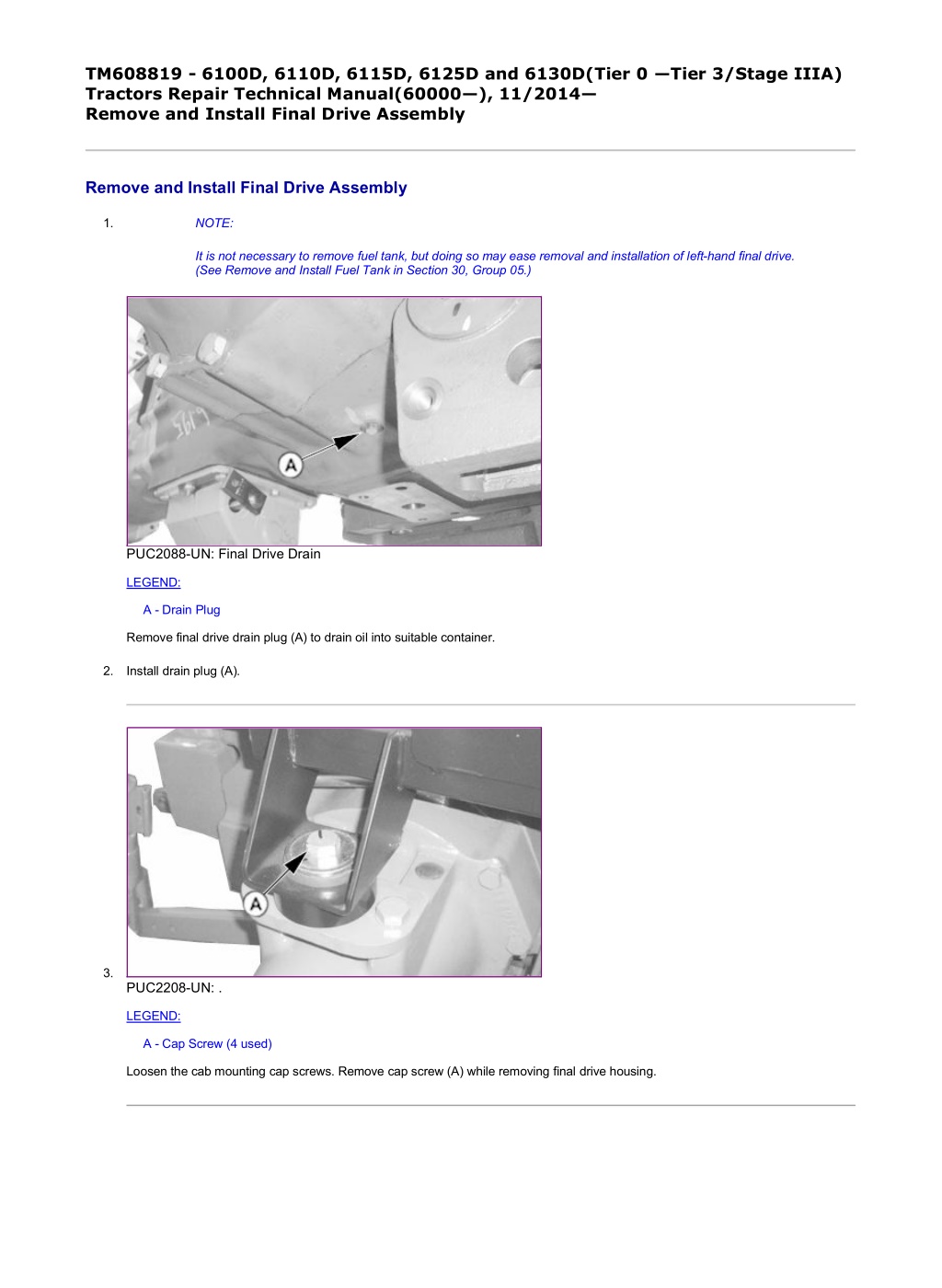
1/9 TM608819 - 6100D, 6110D, 6115D, 6125D and 6130D(Tier 0 Tier 3/Stage IIIA) Tractors Repair Technical Manual(60000 ), 11/2014 Remove and Install Final Drive Assembly Remove and Install Final Drive Assembly 1. NOTE: It is not necessary to remove fuel tank, but doing so may ease removal and installation of left-hand final drive. (See Remove and Install Fuel Tank in Section 30, Group 05.) PUC2088-UN: Final Drive Drain LEGEND: A - Drain Plug Remove final drive drain plug (A) to drain oil into suitable container. 2. Install drain plug (A). 3. PUC2208-UN: . LEGEND: A - Cap Screw (4 used) Loosen the cab mounting cap screws. Remove cap screw (A) while removing final drive housing. file:///C:/ProgramData/Service%20ADVISOR/Temp/TM608819_09001faa829... 2020/7/11
2/9 4. PUC3808-UN: Right-Hand Side Half Axle LEGEND: B - Screw (2 used) C - SCV Mounting Braket Loosen SCV mounting bracket (C) by removing cap screws (B) while removing final drive housing. 5. PY20649-UN: Left Hand Side Half Axle LEGEND: D - Cap Screws E - Transmission Harness F - Bracket Loosen transmission harness bracket (F) by removing cap screws (D) while removing the final drive housing. 6. CAUTION: Prevent bodily injury caused by accidental dropping of tractor when removing wheel. Use jack and floor stands with a minimum capacity of 4540 kg (10,000 lb.). file:///C:/ProgramData/Service%20ADVISOR/Temp/TM608819_09001faa829... 2020/7/11
3/9 PUC2089-UN: Jacking of Tractor Jack tractor from under drawbar support and set jack stands under front of drawbar. 7. CAUTION: The approximate weight of the wheel and tire assembly is 260 kg (573.20 lb.). Item Measurement Specification Wheel and Tire Weight 260 kg (573.20 lb.) Remove left-hand wheel assembly. (See Remove and Install Front and Rear Wheels in Section 80, Group 15.) 8. PY20651-UN: . file:///C:/ProgramData/Service%20ADVISOR/Temp/TM608819_09001faa829... 2020/7/11
https://www.ebooklibonline.com Hello dear friend! Thank you very much for reading. Enter the link into your browser. The full manual is available for immediate download. https://www.ebooklibonline.com
4/9 PY20650-UN: . LEGEND: A - Cotter Pin B - Pin C - Bracket, Link Arm D - Cap Screw (3 used) Remove cotter pin (A) and pin (B). 9. Remove cap screws (D) and link arm bracket (C). 10. PUC2092-UN: . LEGEND: A - Lifting Device B - Eyebolt (2 used) C - Cap Screw (10 used) Install eyebolts (B) into existing holes. 11. Attach a suitable lifting device (A). 12. Remove cap screws (C) and final drive from transaxle. file:///C:/ProgramData/Service%20ADVISOR/Temp/TM608819_09001faa829... 2020/7/11
5/9 13. PUC2093-UN: Final Drive Axle Remove pinion shaft. 14. Inspect all parts for wear or damage. Replace as necessary. 15. Install pinion shaft. 16. PUC2094-UN: Final Drive Mating Surface LEGEND: A - Transaxle Housing Clean mating surfaces of final drive and transaxle housing (A) using TY16285 Cure Primer. 17. Apply TY6304 Flexible Sealant to mating surfaces. 18. NOTE: Gently rotate axle while positioning the final drive pinion into the planetary gears. Install final drive assembly onto transaxle housing. 19. NOTE: Tighten all cap screws, using a crisscross pattern, when housings are mated. Tighten cap screws to specification. Item Measurement Specification file:///C:/ProgramData/Service%20ADVISOR/Temp/TM608819_09001faa829... 2020/7/11
6/9 Final Drives Final Drive Assembly Cap Screw Torque 345 N m (255 lb.-ft.) 20. PY20651-UN: . PY20650-UN: . LEGEND: A - Cotter Pin B - Pin C - Bracket, Link Arm D - Cap Screw (3 used) Install link arm bracket (C) and cap screws (D). 21. Install pin (B) and cotter pin (A). 22. CAUTION: The approximate weight of the wheel and tire assembly is 260 kg (573.20 lb.). Item Measurement Specification Wheel and Tire Weight 260 kg (573.20 lb.) file:///C:/ProgramData/Service%20ADVISOR/Temp/TM608819_09001faa829... 2020/7/11
7/9 Install wheel assembly. (See Remove and Install Front and Rear Wheels in Section 80, Group 15.) 23. PUC2089-UN: Jacking of Tractor Raise tractor using a floor jack under drawbar support; then remove jack stands under front of drawbar. 24. Install fuel tank if previously removed. (See Remove and Install Fuel Tank in Section 30, Group 05.) 25. PUC3808-UN: Right-Hand Side Half Axle LEGEND: B - Screw (2 used) C - SCV Mounting Braket Install screws (B) to install SCV bracket mounting (C). file:///C:/ProgramData/Service%20ADVISOR/Temp/TM608819_09001faa829... 2020/7/11
8/9 26. PY20649-UN: Left Hand Side Half Axle LEGEND: D - Cap Screws E - Transmission Harness F - Bracket Install cap screws (D) to install transmission harness bracket (F). 27. PUC2208-UN: . LEGEND: A - Cap Screw (4 used) Install cab mounting cap screws (A). Tighten to specification. Item Measurement Specification Cab Mounting Cap Screw Torque 610 N m (450 lb.-ft.) file:///C:/ProgramData/Service%20ADVISOR/Temp/TM608819_09001faa829... 2020/7/11
9/9 28. P9073-UN: Sight Glass LEGEND: A - Sight Glass Fill transaxle housing until fluid level is visible between two marks on sight glass (A) with specified transmission/hydraulic oil. (See Section 10 for recommended oil.) 29. Start engine and run for 5 min. 30. Shut off engine and wait 5 min. before rechecking oil level in sight glass. 31. Add additional oil as necessary. Loctite is a trademark of Henkel Corporation AK50421,0000121-19-20141001 file:///C:/ProgramData/Service%20ADVISOR/Temp/TM608819_09001faa829... 2020/7/11
1/4 TM608819 - 6100D, 6110D, 6115D, 6125D and 6130D(Tier 0 Tier 3/Stage IIIA) Tractors Repair Technical Manual(60000 ), 11/2014 Remove, Inspect and Install MFWD Drive Shaft Remove, Inspect and Install MFWD Drive Shaft 1. PUC2096-UN: Rear Shield LEGEND: A - Cap Screw (2 used) B - Shield Loosen cap screws (A) and remove rear shield (B). 2. PUC2097-UN: Front Shield LEGEND: A - Cap Screw (2 used) B - Shield Remove cap screws (A) and front shield (B). file:///C:/ProgramData/Service%20ADVISOR/Temp/TM608819_09001faa826... 2020/7/11
2/4 3. PUC2098-UN: Cap Screw LEGEND: A - Cap Screw (4 used) Remove cap screws (A) and lower shaft to ground. Slide drive shaft off splined output shaft of MFWD drop gearbox. 4. Inspect for wear or damage. Check drive shaft for straightness. Replace as necessary. 5. Apply TY6341 Multi-Purpose SD Polyurea Grease to internal splines of drive shaft end. 6. PUC2099-UN: Drive Shaft LEGEND: A - MFWD Output Shaft B - Drive Shaft Install drive shaft (B) onto MFWD output shaft (A). file:///C:/ProgramData/Service%20ADVISOR/Temp/TM608819_09001faa826... 2020/7/11
3/4 7. PUC2098-UN: . LEGEND: A - Cap Screw (4 used) Install flange to shaft using cap screws (A). 8. PUC2097-UN: Front Shield LEGEND: A - Cap Screw (2 used) B - Shield Install front shield (B) using cap screws (A). file:///C:/ProgramData/Service%20ADVISOR/Temp/TM608819_09001faa826... 2020/7/11
4/4 9. PUC2096-UN: Rear Shield LEGEND: A - Cap Screw (2 used) B - Shield Install rear shield (B) and tighten cap screws (A). OURX984,0000131-19-20140326 file:///C:/ProgramData/Service%20ADVISOR/Temp/TM608819_09001faa826... 2020/7/11
1/2 TM608819 - 6100D, 6110D, 6115D, 6125D and 6130D(Tier 0 Tier 3/Stage IIIA) Tractors Repair Technical Manual(60000 ), 11/2014 Remove and Install MFWD Drop Gearbox Remove and Install MFWD Drop Gearbox 1. PUC2085-UN: MFWD Drop Box Drain PUC2100-UN: . PUC2101-UN: . LEGEND: A - Plug, Drop Gearbox file:///C:/ProgramData/Service%20ADVISOR/Temp/TM608819_09001faa829... 2020/7/11
2/2 B - Cotter Pin (2 used) C - Linkage D - Cap Screw (8 used) Remove drive shaft. (See Remove, Inspect and Install MFWD Drive Shaft in this group.) 2. Remove plug (A) and drain oil. 3. Remove cotter pins (B), and disconnect mechanical front wheel drive engagement linkage (C). 4. Remove cap screws (D) and remove drop gearbox. 5. Make repairs as necessary. (See procedures in this section.) 6. Clean mating surfaces of drop gearbox case and transaxle housing using TY16285 Cure Primer. 7. Apply a coat of TY6304 Flexible Form-in-Place Gasket. 8. Install drop gearbox. Tighten cap screws (D) to specification. Item Measurement Specification Drop Gearbox Mounting Cap Screws Torque 100 150 N m (47 111 lb.-ft.) 9. Install mechanical front wheel drive engagement linkage (C) using cotter pin (B). 10. Install drive shaft. (See Remove, Inspect and Install MFWD Drive Shaft in this group.) 11. P9073-UN: Sight Glass LEGEND: A - Sight Glass Fill transaxle housing until fluid level is visible between two marks on sight glass (A). (See Section 10 for recommended oil.) 12. Start engine and run for 5 min. 13. Shut off engine and wait 5 min. before rechecking oil level in sight glass. 14. Add additional oil as necessary. Loctite is a trademark of Henkel Corporation AK50421,00000FE-19-20141001 file:///C:/ProgramData/Service%20ADVISOR/Temp/TM608819_09001faa829... 2020/7/11
1/5 TM608819 - 6100D, 6110D, 6115D, 6125D and 6130D(Tier 0 Tier 3/Stage IIIA) Tractors Repair Technical Manual(60000 ), 11/2014 Split Tractor Split Tractor 1. PY20652-UN: Steering Lines LEGEND: A - Steering Line B - Oil Cooler Line C - Clamp D - Cap Screw E - Mid Frame Block front wheels. 2. Block front wheel axle. 3. Cab Tractor: Remove cab. (See Remove Operator Cab, in Section 95, Group 00.) 4. OOS Tractor: Remove open operator's station. (See Remove Operator Station, in Section 90, Group 15.) 5. Remove MFWD drive shaft, if equipped. (See Remove, Inspect, and Install MFWD Drive Shaft, in Section 50, Group 05.) 6. Remove fuel tank (See Remove and Install Fuel Tank, Section 30, Group 05.) 7. Drain transmission oil. 8. Perform the following steps on right-hand side of tractor: Identify, label, and disconnect steering oil supply line (A) and oil cooler line (B from mid frame (E). 9. Remove clamp (C) by removing cap screw (D) and remove oil lines (A and B).. file:///C:/ProgramData/Service%20ADVISOR/Temp/TM608819_09001faa829... 2020/7/11
2/5 10. RXA0128540-UN: Support Stands LEGEND: A - Support Stands Place support stands (A) on tractor for stability when separating. 11. PY20653-UN: JDG19 Lifting Brackets file:///C:/ProgramData/Service%20ADVISOR/Temp/TM608819_09001faa829... 2020/7/11
3/5 PY20657-UN: . LEGEND: A - JDG19 Lifting Eyes B - Cap Screws (9 used) C - Cap Screw (1 used) Install JDG19 Lifting Eyes (A) onto clutch housing on both sides of tractor. 12. Attach chains or lift straps to lifting eyes and an overhead lifting device. 13. Remove cap screws (B) attaching mid-frame to fly wheel housing. 14. Remove cap screw (C) from clutch housing side as shown. 15. PY20654-UN: Drive Train Assembly file:///C:/ProgramData/Service%20ADVISOR/Temp/TM608819_09001faa829... 2020/7/11
4/5 LEGEND: A - Drive Train Assembly Carefully separate drive train assembly (A) from fly wheel housing. 16. Install in reverse order. PY20655-UN: Cap Screws PY20656-UN: . LEGEND: A - M20 x 2.5 x 110 Cap Screw (4 used) B - M16 x 2 x 90 Cap Screw (3 used) C - M20 x 2.5 x 90 Cap Screw (2 used) D - M16 x 2 x 70 Cap Screw (1 used) Install cap screws (A, B, C and D) and tighten to specification. Item Measurement Specification Flywheel Housing-to-Clutch Housing Mounting Bolts Torque 542 N m (400 lb.-ft.) file:///C:/ProgramData/Service%20ADVISOR/Temp/TM608819_09001faa829... 2020/7/11
1/1 TM608819 - 6100D, 6110D, 6115D, 6125D and 6130D(Tier 0 Tier 3/Stage IIIA) Tractors Repair Technical Manual(60000 ), 11/2014 PTO Repair Use CTM PTO Repair Use CTM For complete repair information use component technical manual (CTM). Use the appropriate component manual in conjunction with this machine manual. OURX984,000141C-19-20120914 file:///C:/ProgramData/Service%20ADVISOR/Temp/TM608819_09001faa81d... 2020/7/11
1/1 TM608819 - 6100D, 6110D, 6115D, 6125D and 6130D(Tier 0 Tier 3/Stage IIIA) Tractors Repair Technical Manual(60000 ), 11/2014 Other Material Other Material Number Name Use Petroleum Jelly Lubricate PTO Shaft TY6333 (U.S.) Special Purpose HD Moly Grease Lubricate Splines on End of PTO Shaft AC20456,0001890-19-20120828 file:///C:/ProgramData/Service%20ADVISOR/Temp/TM608819_09001faa81d... 2020/7/11
Suggest: If the above button click is invalid. Please download this document first, and then click the above link to download the complete manual. Thank you so much for reading
1/1 TM608819 - 6100D, 6110D, 6115D, 6125D and 6130D(Tier 0 Tier 3/Stage IIIA) Tractors Repair Technical Manual(60000 ), 11/2014 Specifications Specifications Item Measurement Specification Clutch Pedal Free Travel Distance 32 5 mm (1-1/4 3/16 in.) OURX984,0001425-19-20121004 file:///C:/ProgramData/Service%20ADVISOR/Temp/TM608819_09001faa81d... 2020/7/11
https://www.ebooklibonline.com Hello dear friend! Thank you very much for reading. Enter the link into your browser. The full manual is available for immediate download. https://www.ebooklibonline.com