Caterpillar Cat TH220B Telehandler (Prefix SLA) Service Repair Manual Instant Download (SLA00001 and up)
Please open the website below to get the complete manualnn// n

Download Presentation

Please find below an Image/Link to download the presentation.
The content on the website is provided AS IS for your information and personal use only. It may not be sold, licensed, or shared on other websites without obtaining consent from the author. Download presentation by click this link. If you encounter any issues during the download, it is possible that the publisher has removed the file from their server.
E N D
Presentation Transcript
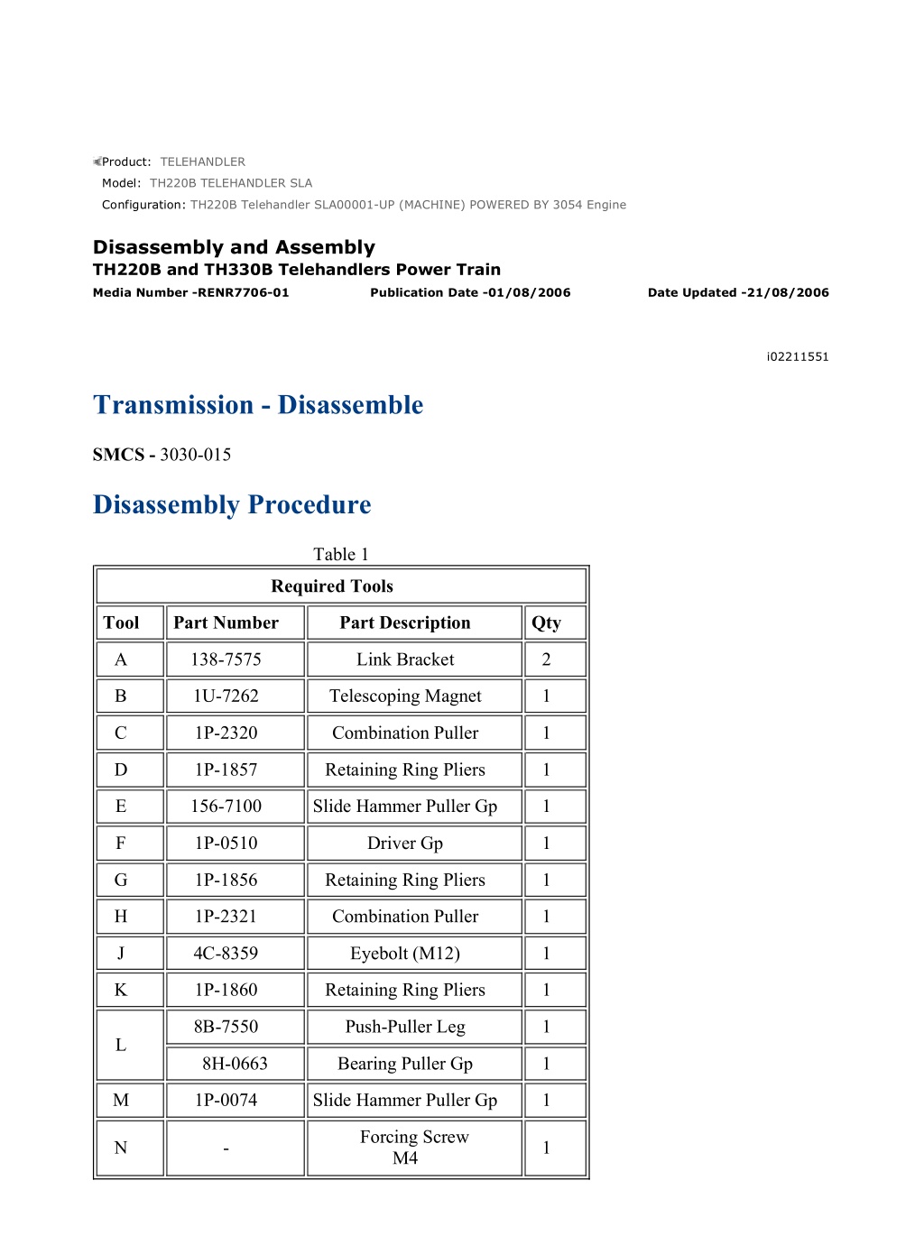
w 1/68(W) Product: TELEHANDLER Model: TH220B TELEHANDLER SLA Configuration: TH220B Telehandler SLA00001-UP (MACHINE) POWERED BY 3054 Engine Disassembly and Assembly TH220B and TH330B Telehandlers Power Train Media Number -RENR7706-01 Publication Date -01/08/2006 Date Updated -21/08/2006 i02211551 Transmission - Disassemble SMCS - 3030-015 Disassembly Procedure Table 1 Required Tools Tool Part Number Part Description Qty A 138-7575 Link Bracket 2 B 1U-7262 Telescoping Magnet 1 C 1P-2320 Combination Puller 1 D 1P-1857 Retaining Ring Pliers 1 E 156-7100 Slide Hammer Puller Gp 1 F 1P-0510 Driver Gp 1 G 1P-1856 Retaining Ring Pliers 1 H 1P-2321 Combination Puller 1 J 4C-8359 Eyebolt (M12) 1 K 1P-1860 Retaining Ring Pliers 1 8B-7550 Push-Puller Leg 1 L 8H-0663 Bearing Puller Gp 1 M 1P-0074 Slide Hammer Puller Gp 1 Forcing Screw M4 N - 1 https://127.0.0.1/sisweb/sisweb/techdoc/techdoc_print_page.jsp?returnurl=/sisweb/sisw... 2022/5/16
w 2/68(W) Start By: A. Remove the transmission and the torque converter. Refer to Disassembly and Assembly, "Transmission and Torque Converter - Remove". NOTICE Care must be taken to ensure that fluids are contained during performance of inspection, maintenance, testing, adjusting and repair of the product. Be prepared to collect the fluid with suitable containers before opening any compartment or disassembling any component containing fluids. Refer to Special Publication, NENG2500, "Caterpillar Tools and Shop Products Guide" for tools and supplies suitable to collect and contain fluids on Caterpillar products. Dispose of all fluids according to local regulations and mandates. Illustration 1 g01116800 1. Remove screws (1) in order to remove sensors (2) . 2. Machines that are equipped with five speeds have additional components that need to be removed. https://127.0.0.1/sisweb/sisweb/techdoc/techdoc_print_page.jsp?returnurl=/sisweb/sisw... 2022/5/16
w 3/68(W) Illustration 2 g01033803 Transmission Position Sensor and Actuator on the Fifth Speed a. Remove screws (3) in order to remove sensor (4) . Illustration 3 g00895262 Personal injury can result from being struck by parts propelled by a released spring force. Make sure to wear all necessary protective equipment. Follow the recommended procedure and use all recommended tooling to release the spring force. b. Remove cap (5) . https://127.0.0.1/sisweb/sisweb/techdoc/techdoc_print_page.jsp?returnurl=/sisweb/sisw... 2022/5/16
https://www.ebooklibonline.com Hello dear friend! Thank you very much for reading. Enter the link into your browser. The full manual is available for immediate download. https://www.ebooklibonline.com
w 4/68(W) Illustration 4 g00895720 c. Remove spring (6). Use Tooling (B) in order to remove detent ball (7) . Illustration 5 g01033827 d. Remove bolts (8). Remove actuator (9) and the O-ring seals from transmission cover (10). Remove screw (11) . Illustration 6 g01033830 https://127.0.0.1/sisweb/sisweb/techdoc/techdoc_print_page.jsp?returnurl=/sisweb/sisw... 2022/5/16
w 5/68(W) e. Remove locking plate (12) in order to remove solenoid (13) from actuator (9). Remove O-ring seals (14) and (15) . f. Remove actuator piston (17) from actuator (9). Remove O-ring seals (16) and (18) . Illustration 7 g01033886 3. Remove bolts (21). Remove actuator (20) and the O-ring seals from transmission housing (19) . Illustration 8 g00892853 4. Remove O-ring seals (22) from actuator (20) . https://127.0.0.1/sisweb/sisweb/techdoc/techdoc_print_page.jsp?returnurl=/sisweb/sisw... 2022/5/16
w 6/68(W) Illustration 9 g01033887 5. Remove neutralizing piston (23) and actuator piston (24) from actuator (20). Remove O- ring seals (25) and (26) . Illustration 10 g01033891 6. Repeat Step 5 for neutralizing piston (27) and actuator piston (28) . 7. Remove screw (30) and locking plate (31) in order to remove solenoids (29) from actuator (20) . https://127.0.0.1/sisweb/sisweb/techdoc/techdoc_print_page.jsp?returnurl=/sisweb/sisw... 2022/5/16
w 7/68(W) Illustration 11 g01033897 8. Remove O-ring seals (33) and (34) . 9. Repeat Step 7 and Step 8 for solenoid (32) . Illustration 12 g00892810 10. Remove bolts (35). Remove actuator (36) and the O-ring seals from transmission cover (10) . 11. Repeat Step 4 to Step 9 for actuator (36) . Illustration 13 g01033899 https://127.0.0.1/sisweb/sisweb/techdoc/techdoc_print_page.jsp?returnurl=/sisweb/sisw... 2022/5/16
w 8/68(W) Illustration 14 g01033901 12. Remove bolts (37) and (40) and washers (38) and (41). Remove drive yokes (39) and (42) from both ends of the output shaft. Illustration 15 g01116695 Illustration 16 g00893167 13. Attach a suitable lifting device to the transmission and position the transmission onto suitable blocking. The weight of the transmission is approximately 230 kg (507 lb). https://127.0.0.1/sisweb/sisweb/techdoc/techdoc_print_page.jsp?returnurl=/sisweb/sisw... 2022/5/16
w 9/68(W) Note: Ensure that the suitable blocking allows clearance between valve housing (43) and the bench. Illustration 17 g01033905 14. Remove bolt (46) and washer (45) in order to remove fan drive (44) and the O-ring seal. Illustration 18 g00893171 15. Remove bolts (47) in order to remove access panel (48) from transmission cover (10) . https://127.0.0.1/sisweb/sisweb/techdoc/techdoc_print_page.jsp?returnurl=/sisweb/sisw... 2022/5/16
w 10/68(W) Illustration 19 g01033909 16. Remove bolt (49) and washer (50). Remove ring (52) from roller bearing (51) . Illustration 20 g01042331 17. Remove temperature sensor (55) from transmission housing (19) . 18. Remove bolt (54) in order to remove speed sensor (53) . Illustration 21 g00896588 https://127.0.0.1/sisweb/sisweb/techdoc/techdoc_print_page.jsp?returnurl=/sisweb/sisw... 2022/5/16
w 11/68(W) 19. Remove O-ring seal (56) from speed sensor (55) . Illustration 22 g00893174 20. Remove bolts (57). Remove modulating valve (58) and the O-ring seals from transmission cover (10) . Illustration 23 g01033922 21. Remove O-ring seals (62) from modulating valve (58). Remove nut (59) and washer (60) in order to remove solenoid (61) . https://127.0.0.1/sisweb/sisweb/techdoc/techdoc_print_page.jsp?returnurl=/sisweb/sisw... 2022/5/16
w 12/68(W) Illustration 24 g01035103 22. Remove valve spool (65) from modulating valve (58). Remove O-ring seals (63) and (64) . Illustration 25 g00893230 23. Remove screws (66) in order to remove idler (67) . Illustration 26 g00893246 https://127.0.0.1/sisweb/sisweb/techdoc/techdoc_print_page.jsp?returnurl=/sisweb/sisw... 2022/5/16
w 13/68(W) Illustration 27 g00893259 24. Use a suitable press in order to take the load off retaining ring (68). Remove retaining ring (68) that secures bearing (69) . Illustration 28 g00893302 25. Use a suitable press in order to remove bearing (69) from mounting flange (70) . Illustration 29 g01116697 https://127.0.0.1/sisweb/sisweb/techdoc/techdoc_print_page.jsp?returnurl=/sisweb/sisw... 2022/5/16
w 14/68(W) 26. Use Tooling (C) and a suitable vise in order to remove bearing (69) from idler (67) . Illustration 30 g00893374 Illustration 31 g00893387 Personal injury can result from being struck by parts propelled by a released spring force. Make sure to wear all necessary protective equipment. Follow the recommended procedure and use all recommended tooling to release the spring force. 27. Remove spring retainers (71), springs (72), and detent balls (73). Use Tooling (B) in order to remove the two detent balls from the transmission housing. Remove O-ring seals (74) from spring retainers (71) . https://127.0.0.1/sisweb/sisweb/techdoc/techdoc_print_page.jsp?returnurl=/sisweb/sisw... 2022/5/16
w 15/68(W) Illustration 32 g00893598 28. Use Tooling (N) in order to remove cap (75) . Illustration 33 g01033936 Typical example of Tooling (B) 29. Make sure that shift rail (76) and shift rail (78) are in the NEUTRAL position. Use Tooling (B) in order to remove detent balls (77) . https://127.0.0.1/sisweb/sisweb/techdoc/techdoc_print_page.jsp?returnurl=/sisweb/sisw... 2022/5/16
w 16/68(W) Illustration 34 g01033941 Note: Record the positions of clips (79) before removing bolts (80) . 30. Remove bolts (80) . 31. Attach Tooling (A) to the holes that are shown in illustration 34. Illustration 35 g01117373 32. Use Tooling (A) and a suitable lifting device in order to lift transmission cover (10). The weight of transmission cover (10) is approximately 42 kg (93 lb). Lift transmission cover (10) away from transmission housing (19) . Note: Ensure that the transmission cover is lifted squarely in order to smoothly disengage the two locating pins that are between the interface of transmission cover (10) and transmission housing (19) . https://127.0.0.1/sisweb/sisweb/techdoc/techdoc_print_page.jsp?returnurl=/sisweb/sisw... 2022/5/16
w 17/68(W) Illustration 36 g01043951 33. Remove O-ring seals (81) from transmission housing (19) . Illustration 37 g00895558 34. Use Tooling (D) in order to remove retaining ring (82). Remove bearing (83) from transmission cover (10) . Illustration 38 g01116701 https://127.0.0.1/sisweb/sisweb/techdoc/techdoc_print_page.jsp?returnurl=/sisweb/sisw... 2022/5/16
w 18/68(W) Illustration 39 g00895560 35. Use Tooling (E) in order to remove bearing cups (84), (85), (86), and (87). Remove any shims that are under bearing cups (84), (85), (86), and (87) . Illustration 40 g00895562 36. Use Tooling (E) in order to remove bearing cup (88) from transmission cover (10). Remove shims (89). Use Tooling (D) in order to remove retaining ring (90) . https://127.0.0.1/sisweb/sisweb/techdoc/techdoc_print_page.jsp?returnurl=/sisweb/sisw... 2022/5/16
w 19/68(W) Illustration 41 g01116702 Illustration 42 g01035172 37. Use Tooling (F) in order to remove seals (91) and (92) from transmission cover (10). Illustration 43 g00895566 38. Remove bearing carrier (93) . https://127.0.0.1/sisweb/sisweb/techdoc/techdoc_print_page.jsp?returnurl=/sisweb/sisw... 2022/5/16
w 20/68(W) Illustration 44 g01033958 39. Remove screws (95). Remove tube assembly (94) and the O-ring seals. Note: The position of the oil tube in a transmission with five speeds is different to the position of the oil tube for a transmission with four speeds. 40. Repeat Step 39 for the other tube assembly. Illustration 45 g01033960 Cover of a transmission with four speeds a. Remove screws (97) in order to remove tube assembly (96) . Illustration 46 g01033964 Cover of a transmission with five speeds b. Remove screws (99). Remove tube assembly (98) and the O-ring seals. https://127.0.0.1/sisweb/sisweb/techdoc/techdoc_print_page.jsp?returnurl=/sisweb/sisw... 2022/5/16
w 21/68(W) Illustration 47 g01042376 41. Remove thrust bearing (100) and sleeve (101) from input shaft (102) . Illustration 48 g00893604 42. Remove input shaft (102) . Illustration 49 g00893605 https://127.0.0.1/sisweb/sisweb/techdoc/techdoc_print_page.jsp?returnurl=/sisweb/sisw... 2022/5/16
w 22/68(W) 43. Use Tooling (K) in order to remove retaining ring (103). Remove gear (104) from input shaft (102) . Illustration 50 g00893606 44. Remove ring seal (105) from input shaft (102) . Illustration 51 g00893607 45. Use a suitable press in order to remove bearing race (106) from input shaft (102) . https://127.0.0.1/sisweb/sisweb/techdoc/techdoc_print_page.jsp?returnurl=/sisweb/sisw... 2022/5/16
Suggest: For more complete manuals. Please go to the home page. https://www.ebooklibonline.com If the above button click is invalid. Please download this document first, and then click the above link to download the complete manual. Thank you so much for reading
w 23/68(W) Illustration 52 g01042432 46. Remove roller bearing (107) from transmission housing (19) . Illustration 53 g00893609 47. Remove fan drive shaft (108) . Illustration 54 g01042449 48. Remove bearing cup (109) from transmission housing (19) . https://127.0.0.1/sisweb/sisweb/techdoc/techdoc_print_page.jsp?returnurl=/sisweb/sisw... 2022/5/16
w 24/68(W) Illustration 55 g00893610 49. Remove ring seal (110) from fan drive shaft (108) . Illustration 56 g01116704 50. Use Tooling (H) in order to remove idler gear (113), thrust washer (112), and bearing cone (111) from fan drive shaft (108) . https://127.0.0.1/sisweb/sisweb/techdoc/techdoc_print_page.jsp?returnurl=/sisweb/sisw... 2022/5/16
https://www.ebooklibonline.com Hello dear friend! Thank you very much for reading. Enter the link into your browser. The full manual is available for immediate download. https://www.ebooklibonline.com