Caterpillar Cat D6R2 TRACK-TYPE TRACTOR STD, XL, LGP (Prefix TTT) Service Repair Manual Instant Download (TTT00001 and up)
Please open the website below to get the complete manualnn// n

Download Presentation

Please find below an Image/Link to download the presentation.
The content on the website is provided AS IS for your information and personal use only. It may not be sold, licensed, or shared on other websites without obtaining consent from the author. Download presentation by click this link. If you encounter any issues during the download, it is possible that the publisher has removed the file from their server.
E N D
Presentation Transcript
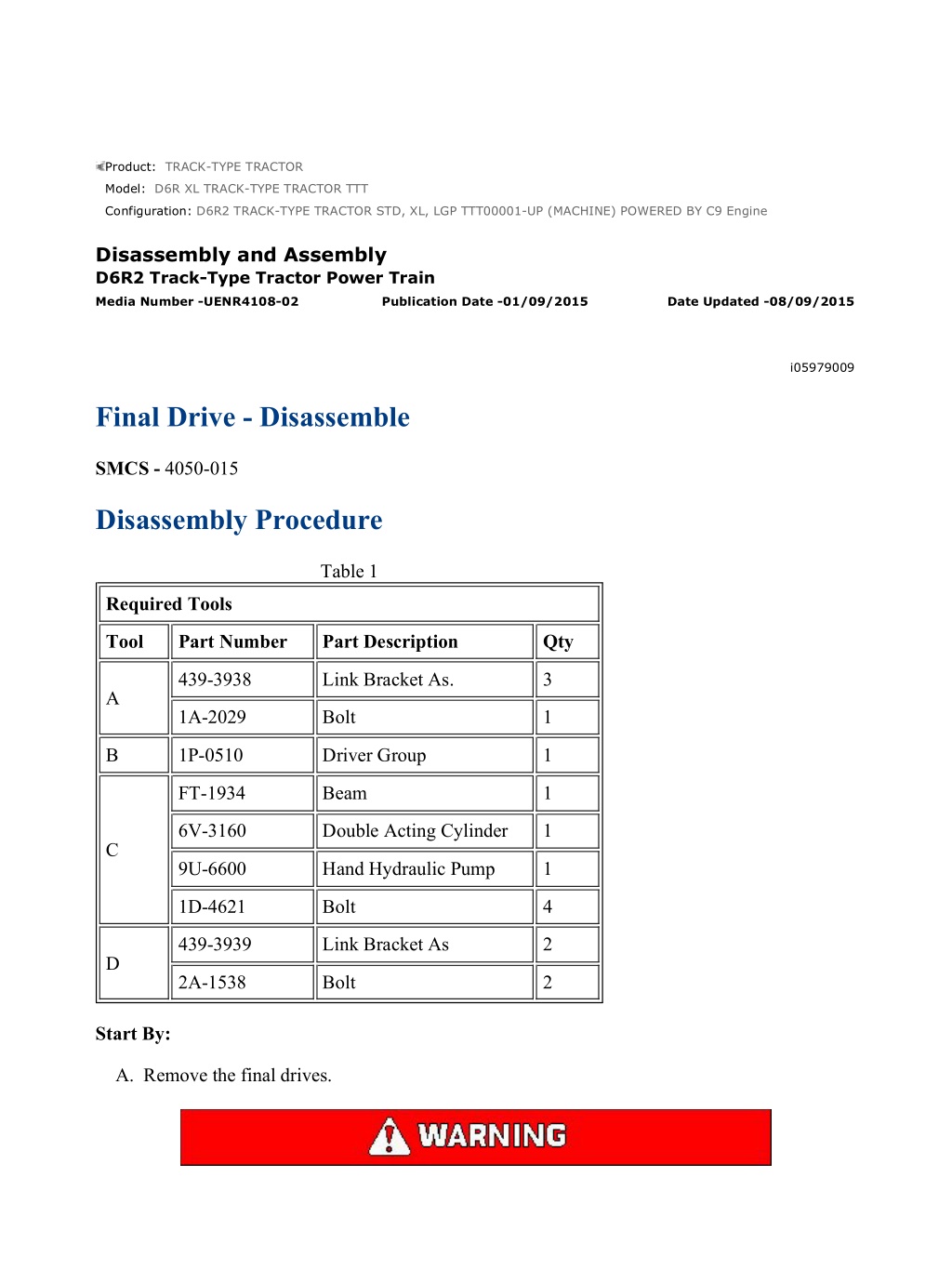
D6R2 TRACK-TYPE TRACTOR STD, XL, LGP TTT00001-UP (MACHINE) POW... 1/7 Product: TRACK-TYPE TRACTOR Model: D6R XL TRACK-TYPE TRACTOR TTT Configuration: D6R2 TRACK-TYPE TRACTOR STD, XL, LGP TTT00001-UP (MACHINE) POWERED BY C9 Engine Disassembly and Assembly D6R2 Track-Type Tractor Power Train Media Number -UENR4108-02 Publication Date -01/09/2015 Date Updated -08/09/2015 i05979009 Final Drive - Disassemble SMCS - 4050-015 Disassembly Procedure Table 1 Required Tools Tool Part Number Part Description Qty 439-3938 Link Bracket As. 3 A 1A-2029 Bolt 1 B 1P-0510 Driver Group 1 FT-1934 Beam 1 6V-3160 Double Acting Cylinder 1 C 9U-6600 Hand Hydraulic Pump 1 1D-4621 Bolt 4 439-3939 Link Bracket As 2 D 2A-1538 Bolt 2 Start By: A. Remove the final drives. https://127.0.0.1/sisweb/sisweb/techdoc/techdoc_print_page.jsp?returnurl=/sis... 2021/11/29
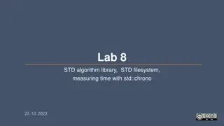
D6R2 TRACK-TYPE TRACTOR STD, XL, LGP TTT00001-UP (MACHINE) POW... 2/7 When you are using hydraulic cylinders and puller studs, always ensure that the rated capacity of the puller stud meets or exceeds the rated capacity of the hydraulic cylinder. If the puller stud does not meet or exceed the rated capacity of the hydraulic cylinder, a sudden failure of the puller stud could occur. The sudden failure of the puller stud could result in personal injury or death. Illustration 1 g01195912 1. Attach Tooling (A) and a suitable lifting device to planetary carrier (3) . 2. Remove bolts (1). Remove planetary carrier (3) and the two O-ring seals from the hub. The weight of planetary carrier (3) is approximately 137 kg (302 lb). 3. Remove retainers (2) . https://127.0.0.1/sisweb/sisweb/techdoc/techdoc_print_page.jsp?returnurl=/sis... 2021/11/29
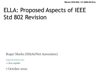
D6R2 TRACK-TYPE TRACTOR STD, XL, LGP TTT00001-UP (MACHINE) POW... 3/7 Illustration 2 g00841089 4. Place support under planetary carrier (3) in order to prevent damage. Use Tooling (B) and a suitable press to remove the planetary gear shafts. 5. Remove planetary gears (4) from planetary carrier (3) . Illustration 3 g00841091 6. Remove bearing cones (5) from gears (4) . 7. Remove the bearing cups from each side of the gears. Illustration 4 g00841092 https://127.0.0.1/sisweb/sisweb/techdoc/techdoc_print_page.jsp?returnurl=/sis... 2021/11/29
https://www.ebooklibonline.com Hello dear friend! Thank you very much for reading. Enter the link into your browser. The full manual is available for immediate download. https://www.ebooklibonline.com
D6R2 TRACK-TYPE TRACTOR STD, XL, LGP TTT00001-UP (MACHINE) POW... 4/7 Illustration 5 g01195913 8. Remove bolts (6) and retainer (7) . 9. Attach a suitable lifting device to hub (12) and ring gear (8). The weight of hub (12) and ring gear (8) is approximately 68 kg (150 lb). Remove hub (12) and ring gear (8) . Illustration 6 g01195915 10. Turn over hub (9) and ring gear (8). Remove retaining ring (10). Attach a suitable lifting device to hub (9). The weight of hub (9) is approximately 37 kg (82 lb). The weight of ring gear (8) is approximately 32 kg (71 lb). Remove hub (9) . https://127.0.0.1/sisweb/sisweb/techdoc/techdoc_print_page.jsp?returnurl=/sis... 2021/11/29
D6R2 TRACK-TYPE TRACTOR STD, XL, LGP TTT00001-UP (MACHINE) POW... 5/7 Illustration 7 g00841095 11. Install Tooling (C) on hub (12). Note: Do not lift hub (12) too high. Do not allow hub (12) to contact the fitting on the hydraulic cylinder. 12. Use Tooling (C) to loosen hub (12) from spindle (13). Remove Tooling (C) . 13. Remove bearing cone (11) . Illustration 8 g01195917 14. Attach Tooling (D) and a suitable lifting device to hub (12). Remove hub (12) from spindle (13). The weight of hub (12) is approximately 180 kg (397 lb). https://127.0.0.1/sisweb/sisweb/techdoc/techdoc_print_page.jsp?returnurl=/sis... 2021/11/29
D6R2 TRACK-TYPE TRACTOR STD, XL, LGP TTT00001-UP (MACHINE) POW... 6/7 Illustration 9 g00841099 15. Turn over hub (12). Remove Duo-Cone seal kit (15). Use a suitable hammer and a suitable punch to remove bearing cup (16) . 16. Turn over hub (12). Remove bearing cup (14) from the hub. Note: If the Duo-Cone seal will be reused, mark the seal kits for installation purposes. Illustration 10 g00841101 Note: Bearing cone (18) may be damaged if the bearing cone is removed from spindle (13) . 17. Remove Duo-Cone seal (19) from spindle (13) . 18. If necessary, remove bearing cone (18) from the spindle. 19. Remove lip seal (17) from spindle (13) . https://127.0.0.1/sisweb/sisweb/techdoc/techdoc_print_page.jsp?returnurl=/sis... 2021/11/29
D6R2 TRACK-TYPE TRACTOR STD, XL, LGP TTT00001-UP (MACHINE) POW... 1/7 Disassembly and Assembly D6R2 Track-Type Tractor Power Train Media Number -UENR4108-02 Publication Date -01/09/2015 Date Updated -08/09/2015 i06268547 Final Drive - Assemble SMCS - 4050-016 Assembly Procedure Table 1 Required Tools Tool Part Number Part Description Qty 439-3938 Link Bracket As. 3 A 1A-2029 Bolt 3 B 1P-0510 Driver Group 1 439-3939 Link Bracket As. 2 D 2A-1538 Bolt 2 E 1U-6437 Duo-Cone Seal Installer As 1 1. Apply clean oil to all the parts during assembly. https://127.0.0.1/sisweb/sisweb/techdoc/techdoc_print_page.jsp?returnurl=/sis... 2021/11/29
D6R2 TRACK-TYPE TRACTOR STD, XL, LGP TTT00001-UP (MACHINE) POW... 2/7 Illustration 1 g00841209 2. Use Tooling (B) to install lip seal (17) in spindle (13) to a minimum depth of 9.65 mm (0.400 inch). Do not apply excessive force to lip seal (17) during installation in order to avoid damaging the seal. Put clean oil on the lip of the seal. 3. Raise the temperature of bearing cone (18) to a maximum temperature of 135 C (275 F). Install bearing cone (18) on spindle (13) . Note: Before the installation of the Duo-Cone seal, refer to Disassembly and Assembly, "Duo-Cone Conventional Seals - Install" for the correct procedure. 4. Use Tooling (E) to install the Duo-Cone seal on spindle (13) . Illustration 2 g00841210 5. Lower the temperature of bearing cups (14) and (16). Install bearing cups (14) and (16) in hub (12) . 6. Use Tooling (E) to install the Duo-Cone seal in hub (12) . https://127.0.0.1/sisweb/sisweb/techdoc/techdoc_print_page.jsp?returnurl=/sis... 2021/11/29
D6R2 TRACK-TYPE TRACTOR STD, XL, LGP TTT00001-UP (MACHINE) POW... 3/7 Illustration 3 g01195917 7. Attach Tooling (D) to hub (12). Attach a suitable lifting device to Tooling (D). Carefully position hub (12) on spindle (13) . Illustration 4 g00841212 8. Raise the temperature of bearing cone (11). Install bearing cone (11) on spindle (13). Illustration 5 g03879977 https://127.0.0.1/sisweb/sisweb/techdoc/techdoc_print_page.jsp?returnurl=/sis... 2021/11/29
D6R2 TRACK-TYPE TRACTOR STD, XL, LGP TTT00001-UP (MACHINE) POW... 4/7 9. Using two people, install hub (9) onto spindle (13). Place five washers onto hub (9) next to but not touching spindle (13) . 10. Install retainer (7) and bolts (6). While hub (12) is slowly rotated, tighten bolts (6) evenly to a torque of 135 15 N m (100 11 lb ft). 11. Remove bolts (6), remove retainer (7), remove the washers, and use two people to remove hub (9) . Illustration 6 g01195915 12. Attach a suitable lifting device to hub (9) and position hub (9) in ring gear (8). Install retaining ring (10) . Illustration 7 g01195913 13. Turn over hub (9) and ring gear (8). Attach a suitable lifting device to hub (9) and the ring gear (8) into position in hub (12). https://127.0.0.1/sisweb/sisweb/techdoc/techdoc_print_page.jsp?returnurl=/sis... 2021/11/29
D6R2 TRACK-TYPE TRACTOR STD, XL, LGP TTT00001-UP (MACHINE) POW... 5/7 Illustration 8 g03879627 14. Install retainer (7) and bolts (6). While hub (12) is slowly rotated, tighten bolts (6) evenly to a torque of 135 15 N m (100 11 lb ft). After tightening bolts (6), there must be a gap of 0.08 0.05 mm (0.003 0.002 inch) between retainer (7) and hub (9). Also, retainer (7) must contact the end of spindle (13) (not shown). If the required gap cannot be reached or retainer (7) does not contact spindle (13) (not shown) then repeat Step 9 through Step 11. Illustration 9 g00841091 15. Lower the temperature of the bearing cups. Install the bearing cups in three planetary gears (4) . 16. Install bearing cones (5) . https://127.0.0.1/sisweb/sisweb/techdoc/techdoc_print_page.jsp?returnurl=/sis... 2021/11/29
D6R2 TRACK-TYPE TRACTOR STD, XL, LGP TTT00001-UP (MACHINE) POW... 6/7 Illustration 10 g03745454 17. Position planetary carrier (3) in a suitable press. Position planetary gear (4) in planetary carrier (3) . NOTICE The shaft must be correctly installed. If the shaft is incorrectly installed, the bearing preload will be incorrect. This will result in component damage. 18. Lower the temperature of the shafts. Use Tooling (B) and a suitable press to install the shafts in planetary carrier (3). Illustration 11 g03881683 19. After the installation, measure distance (X) between planetary carrier (3) and the planetary shaft. The planetary shaft should extend 0.08 0.05 mm (0.003 0.002 inch) past the surface of the carrier to provide the correct bearing preload. The gear must rotate by hand after installation. If the gear does not rotate, the problem must be corrected. Repeat this procedure for all three shafts. Repeat this procedure for all three shafts. https://127.0.0.1/sisweb/sisweb/techdoc/techdoc_print_page.jsp?returnurl=/sis... 2021/11/29
D6R2 TRACK-TYPE TRACTOR STD, XL, LGP TTT00001-UP (MACHINE) POW... 7/7 Illustration 12 g03881705 20. Install the O-ring seals and retainers (2). Tighten the bolts to a torque of 240 40 N m (177 30 lb ft). The gears must rotate by hand after installation. If the gear does not rotate, the problem can be corrected by driving retainers (2) toward planetary carrier (3) . Illustration 13 g03881724 21. Attach Tooling (A) and a suitable lifting device. Install the two O-ring seals onto planetary carrier (3). Align the drain hole in the planetary carrier with the drain hole in the hub. 22. Position the planetary carrier in the hub. 23. Install bolts (1) that hold planetary carrier (3) to the hub. Tighten bolts (1) to a torque of 430 60 N m (317 44 lb ft). Remove Tooling (A) . End By: Install the final drives. https://127.0.0.1/sisweb/sisweb/techdoc/techdoc_print_page.jsp?returnurl=/sis... 2021/11/29
D6R2 TRACK-TYPE TRACTOR STD, XL, LGP TTT00001-UP (MACHINE) POW... 1/10 Product: TRACK-TYPE TRACTOR Model: D6R XL TRACK-TYPE TRACTOR TTT Configuration: D6R2 TRACK-TYPE TRACTOR STD, XL, LGP TTT00001-UP (MACHINE) POWERED BY C9 Engine Disassembly and Assembly D6R2 Track-Type Tractor Power Train Media Number -UENR4108-02 Publication Date -01/09/2015 Date Updated -08/09/2015 i05979633 Final Drive, Steering Differential, and Brake (Left Side) - Remove and Install SMCS - 4050-010-LT; 4132-010-LT Removal Procedure Table 1 Required Tools Tool Part Number Description Qty FT-1952 Axle Removal Tool 1 A 1U-7432 Adapter Assembly 1 8T-3207 Lifting Bracket 1 5P-8622 Shackle 1 B 1D-4615 Bolt 2 1B-4331 Nut 2 5P-8248 Washer 4 C 1B-4331 Nut 1 5P-8248 Washer 2 439-3939 Link Bracket As. 1 439-3940 Link Bracket As. 1 386-6031 Lever Hoist 1 1A-1460 Bolt 1 5P-8245 Washer 1 https://127.0.0.1/sisweb/sisweb/techdoc/techdoc_print_page.jsp?returnurl=/sis... 2021/11/29
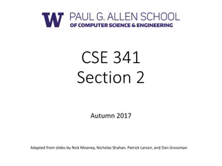
D6R2 TRACK-TYPE TRACTOR STD, XL, LGP TTT00001-UP (MACHINE) POW... 2/10 1A-8063 Bolt 1 D 5B-4274 Bolt 3 Start By: A. Separate the track. B. Remove the drive axles. C. Remove the steering motor. 1. Drain the oil from the final drive. Refer to Operation and Maintenance Manual, "Final Drive Oil - Change" for the proper draining and filling procedure. Illustration 1 g01127146 2. Remove bolts (1) from adapter (2) . 3. Install Tooling (D) in Holes (X). Remove adapter (2) . https://127.0.0.1/sisweb/sisweb/techdoc/techdoc_print_page.jsp?returnurl=/sis... 2021/11/29
D6R2 TRACK-TYPE TRACTOR STD, XL, LGP TTT00001-UP (MACHINE) POW... 3/10 Illustration 2 g01127151 4. Remove O-ring seal (3) from adapter (2) . https://127.0.0.1/sisweb/sisweb/techdoc/techdoc_print_page.jsp?returnurl=/sis... 2021/11/29
D6R2 TRACK-TYPE TRACTOR STD, XL, LGP TTT00001-UP (MACHINE) POW... 4/10 Illustration 3 g01127160 https://127.0.0.1/sisweb/sisweb/techdoc/techdoc_print_page.jsp?returnurl=/sis... 2021/11/29
D6R2 TRACK-TYPE TRACTOR STD, XL, LGP TTT00001-UP (MACHINE) POW... 5/10 Illustration 4 g01127169 5. Insert Tooling (A) 940 mm (37.0 inch) into the final drive housing. Use Tooling (A) to slide the sliding carrier off the bevel gear shaft. 6. Rotate Tooling (A) by 180 degrees. 7. Pull Tooling (A) until the sliding carrier stops. 8. Rotate Tooling (A) by 180 degrees and remove Tooling (A) . https://127.0.0.1/sisweb/sisweb/techdoc/techdoc_print_page.jsp?returnurl=/sis... 2021/11/29
D6R2 TRACK-TYPE TRACTOR STD, XL, LGP TTT00001-UP (MACHINE) POW... 6/10 Illustration 5 g01127173 https://127.0.0.1/sisweb/sisweb/techdoc/techdoc_print_page.jsp?returnurl=/sis... 2021/11/29
D6R2 TRACK-TYPE TRACTOR STD, XL, LGP TTT00001-UP (MACHINE) POW... 7/10 Illustration 6 g01127177 9. Adjust Tooling (B) as shown in Illustration 5. Remove two bolts (4). Discard bolts (4). Install Tooling (B) and a suitable lifting device. The weight of the final drive, the differential, and the brake is approximately 730 kg (1610 lb). 10. Remove seven bolts (5). Install Tooling (C) . https://127.0.0.1/sisweb/sisweb/techdoc/techdoc_print_page.jsp?returnurl=/sis... 2021/11/29
Suggest: For more complete manuals. Please go to the home page. https://www.ebooklibonline.com If the above button click is invalid. Please download this document first, and then click the above link to download the complete manual. Thank you so much for reading
D6R2 TRACK-TYPE TRACTOR STD, XL, LGP TTT00001-UP (MACHINE) POW... 8/10 Illustration 7 g01127323 11. Remove remaining bolts (5) and bolts (7). Do not remove bolts (6) . https://127.0.0.1/sisweb/sisweb/techdoc/techdoc_print_page.jsp?returnurl=/sis... 2021/11/29
D6R2 TRACK-TYPE TRACTOR STD, XL, LGP TTT00001-UP (MACHINE) POW... 9/10 Illustration 8 g01127327 12. Pull outward on final drive (9), steering differential (10), and brake (11) by approximately 25 mm (1.0 inch). Final drive (9), steering differential (10), and brake (11) should move freely. 13. Use Tooling (C) in order to rotate final drive (9), steering differential (10), and brake (11) by 45 to 60 degrees counterclockwise. 14. Remove final drive (9), steering differential (10), and brake (11) . 15. Remove O-ring seals (8) . Installation Procedure 1. Install final drive (9), steering differential (10), and brake (11) in the reverse order of removal. a. Tighten bolts (5) to a torque of 800 90 N m (590 66 lb ft). b. Lubricate two new sprocket segment bolts (4) with SAE 30 oil. Install new sprocket segment bolts (4) . c. Tighten bolts (4) to a torque of (4) to a torque of 175 40 N m (130 30 lb ft). Tighten bolts (4) for another 1/3 turn. The final torque for bolts (4) must be a minimum of 380 N m (280 lb ft). https://127.0.0.1/sisweb/sisweb/techdoc/techdoc_print_page.jsp?returnurl=/sis... 2021/11/29
https://www.ebooklibonline.com Hello dear friend! Thank you very much for reading. Enter the link into your browser. The full manual is available for immediate download. https://www.ebooklibonline.com
")
")
")

")
")
")
")
")
")
")
")
")
")
")
")
")
")
")
")
")

")
")