Caterpillar Cat CB64B Vibratory Compactor (Prefix 477) Service Repair Manual Instant Download (47700001 and up)
Please open the website below to get the complete manualnn//
Download Presentation

Please find below an Image/Link to download the presentation.
The content on the website is provided AS IS for your information and personal use only. It may not be sold, licensed, or shared on other websites without obtaining consent from the author. Download presentation by click this link. If you encounter any issues during the download, it is possible that the publisher has removed the file from their server.
E N D
Presentation Transcript
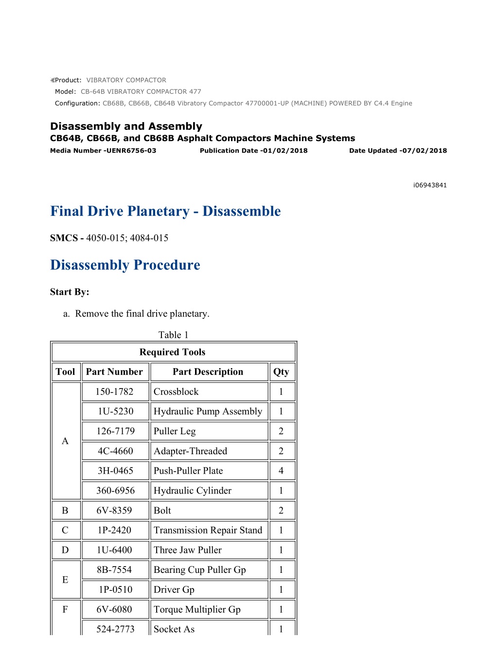
CB68B, CB66B, CB64B Vibratory Compactor 47700001-UP (MACHINE) POWERE... 1/14 Product: VIBRATORY COMPACTOR Model: CB-64B VIBRATORY COMPACTOR 477 Configuration: CB68B, CB66B, CB64B Vibratory Compactor 47700001-UP (MACHINE) POWERED BY C4.4 Engine Disassembly and Assembly CB64B, CB66B, and CB68B Asphalt Compactors Machine Systems Media Number -UENR6756-03 Publication Date -01/02/2018 Date Updated -07/02/2018 i06943841 Final Drive Planetary - Disassemble SMCS - 4050-015; 4084-015 Disassembly Procedure Start By: a. Remove the final drive planetary. Table 1 Required Tools Tool Part Number Part Description Qty 150-1782 Crossblock 1 1U-5230 Hydraulic Pump Assembly 1 126-7179 Puller Leg 2 A 4C-4660 Adapter-Threaded 2 3H-0465 Push-Puller Plate 4 360-6956 Hydraulic Cylinder 1 B 6V-8359 Bolt 2 C 1P-2420 Transmission Repair Stand 1 D 1U-6400 Three Jaw Puller 1 8B-7554 Bearing Cup Puller Gp 1 E 1P-0510 Driver Gp 1 F 6V-6080 Torque Multiplier Gp 1 524-2773 Socket As 1 https://127.0.0.1/sisweb/sisweb/techdoc/techdoc_print_page.jsp?returnurl=/sisw... 2023/3/6
CB68B, CB66B, CB64B Vibratory Compactor 47700001-UP (MACHINE) POWERE... 2/14 1U-9889 Crossblock 1 4C-5660 Adapter-Threaded 2 G 5F-7369 Puller Leg 2 3H-0465 Push-Puller Plate 2 5P-5247 Hydraulic Puller As 1 H 439-3939 Link Bracket As 3 1U-9889 Crossblock 1 3H-0469 Leg 2 3H-0465 Push-Puller Plate 4 J 1P-0520 Driver Gp 1 360-6964 Hydraulic Cylinder 1 1U-5230 Hydraulic Pump Assembly 1 Illustration 1 g06172670 Illustration 2 g06172710 https://127.0.0.1/sisweb/sisweb/techdoc/techdoc_print_page.jsp?returnurl=/sisw... 2023/3/6
CB68B, CB66B, CB64B Vibratory Compactor 47700001-UP (MACHINE) POWERE... 3/14 Personal injury can result from being struck by parts propelled by a released spring force. Make sure to wear all necessary protective equipment. Follow the recommended procedure and use all recommended tooling to release the spring force. 1. Remove bolts (1), flange (2), and the O-ring seal. 2. Use Tooling (A) to compress the plate away from retaining ring (3). 3. Remove retaining ring (3) and release pressure from Tooling (A). Remove Tooling (A). Illustration 3 g06172716 4. Remove plate (4). Illustration 4 g06172729 5. Remove springs (5). https://127.0.0.1/sisweb/sisweb/techdoc/techdoc_print_page.jsp?returnurl=/sisw... 2023/3/6
https://www.ebooklibonline.com Hello dear friend! Thank you very much for reading. Enter the link into your browser. The full manual is available for immediate download. https://www.ebooklibonline.com
CB68B, CB66B, CB64B Vibratory Compactor 47700001-UP (MACHINE) POWERE... 4/14 Illustration 5 g06172730 6. Use Tooling (B) to remove piston (6). Illustration 6 g06172740 7. Remove discs (7) and the shims. Illustration 7 g06172742 8. Remove backup rings (8) and O-ring seals (9). https://127.0.0.1/sisweb/sisweb/techdoc/techdoc_print_page.jsp?returnurl=/sisw... 2023/3/6
CB68B, CB66B, CB64B Vibratory Compactor 47700001-UP (MACHINE) POWERE... 5/14 Illustration 8 g06172653 9. Secure the final drive to Tooling (C) or a suitable bench. The weight of the final drive is approximately 110 kg (243 lb). 10. Remove bolts (10) and cover (11). Illustration 9 g06172743 11. Remove O-ring seal (13), bolts (14), and gear (15). Illustration 10 g06172748 12. Remove O-ring seal (16) from gear (15). https://127.0.0.1/sisweb/sisweb/techdoc/techdoc_print_page.jsp?returnurl=/sisw... 2023/3/6
CB68B, CB66B, CB64B Vibratory Compactor 47700001-UP (MACHINE) POWERE... 6/14 Illustration 11 g06172753 13. Remove gear (17) and carrier assembly (18). Illustration 12 g06172755 14. Remove retaining ring (19) and gear (17) from shaft (20). Illustration 13 g06172752 15. Remove retaining rings (21). https://127.0.0.1/sisweb/sisweb/techdoc/techdoc_print_page.jsp?returnurl=/sisw... 2023/3/6
CB68B, CB66B, CB64B Vibratory Compactor 47700001-UP (MACHINE) POWERE... 7/14 Illustration 14 g06172757 16. Use Tooling (D) to remove gears (22). Illustration 15 g06172761 17. Remove retaining ring (24) and gear (23) from carrier assembly (18). Illustration 16 g06172762 18. Remove carrier assembly (25). https://127.0.0.1/sisweb/sisweb/techdoc/techdoc_print_page.jsp?returnurl=/sisw... 2023/3/6
CB68B, CB66B, CB64B Vibratory Compactor 47700001-UP (MACHINE) POWERE... 8/14 Illustration 17 g06172766 19. Remove spacer (26) and retaining rings (27) from carrier assembly (25). Illustration 18 g06172767 20. Use Tooling (B) to remove gears (28) from carrier assembly (25). Illustration 19 g06172771 21. Remove gear (29). https://127.0.0.1/sisweb/sisweb/techdoc/techdoc_print_page.jsp?returnurl=/sisw... 2023/3/6
CB68B, CB66B, CB64B Vibratory Compactor 47700001-UP (MACHINE) POWERE... 9/14 Illustration 20 g06172772 22. Use pry bars to remove gear (30). Illustration 21 g06172773 23. Remove retaining rings (31). Illustration 22 g06172774 https://127.0.0.1/sisweb/sisweb/techdoc/techdoc_print_page.jsp?returnurl=/sisw... 2023/3/6
CB68B, CB66B, CB64B Vibratory Compactor 47700001-UP (MACHINE) POWE... 10/14 24. Use Tooling (E) to remove gears (32). Illustration 23 g06172775 Illustration 24 g06172776 Personal injury can result from being struck by parts propelled by a released spring force. Make sure to wear all necessary protective equipment. Follow the recommended procedure and use all recommended tooling to release the spring force. 25. Use Tooling (F) to remove bearing locknut (33). https://127.0.0.1/sisweb/sisweb/techdoc/techdoc_print_page.jsp?returnurl=/sisw... 2023/3/6
CB68B, CB66B, CB64B Vibratory Compactor 47700001-UP (MACHINE) POWE... 11/14 Illustration 25 g06172777 Illustration 26 g06172778 26. Use Tooling (G) to separate hub (34). 27. Use Tooling (H) and a suitable lifting device to remove hub (34). The weight of hub (34) is approximately 37 kg (80 lb). Illustration 27 g06172910 28. Remove bearing cone (35) from hub (34). https://127.0.0.1/sisweb/sisweb/techdoc/techdoc_print_page.jsp?returnurl=/sisw... 2023/3/6
CB68B, CB66B, CB64B Vibratory Compactor 47700001-UP (MACHINE) POWE... 12/14 Illustration 28 g06172779 29. Remove duo-cone seal (36) from hub (34). Illustration 29 g06172906 30. Remove bearing cups (37) from hub (34). Illustration 30 g06173076 31. Use Tooling (J) to remove spacer (38) and bearing cone (39). https://127.0.0.1/sisweb/sisweb/techdoc/techdoc_print_page.jsp?returnurl=/sisw... 2023/3/6
CB68B, CB66B, CB64B Vibratory Compactor 47700001-UP (MACHINE) POWE... 13/14 Illustration 31 g06173085 32. Remove duo-cone seal (40) from spindle (41). Illustration 32 g06173089 33. Remove retaining ring (42) from spindle (41). 34. Use a soft faced hammer to remove shaft assembly (43) from the opposite side on spindle (41). Illustration 33 g06173098 35. Remove retaining ring (44) and roller bearing (45) from shaft assembly (43). https://127.0.0.1/sisweb/sisweb/techdoc/techdoc_print_page.jsp?returnurl=/sisw... 2023/3/6
CB68B, CB66B, CB64B Vibratory Compactor 47700001-UP (MACHINE) POWERE... 1/13 Product: VIBRATORY COMPACTOR Model: CB-64B VIBRATORY COMPACTOR 477 Configuration: CB68B, CB66B, CB64B Vibratory Compactor 47700001-UP (MACHINE) POWERED BY C4.4 Engine Disassembly and Assembly CB64B, CB66B, and CB68B Asphalt Compactors Machine Systems Media Number -UENR6756-03 Publication Date -01/02/2018 Date Updated -07/02/2018 i06943843 Final Drive Planetary - Assemble SMCS - 4050-016; 4084-016 Assembly Procedure Table 1 Required Tools Tool Part Number Part Description Qty 150-1782 Crossblock 1 1U-5230 Hydraulic Pump Assembly 1 126-7179 Puller Leg 2 A 4C-4660 Adapter-Threaded 2 3H-0465 Push-Puller Plate 4 360-6956 Hydraulic Cylinder 1 C 1P-2420 Transmission Repair Stand 1 6V-6080 Torque Multiplier Gp 1 F 524-2773 Socket As 1 H 439-3939 Link Bracket As 3 K 1U-6438 Duo-Cone Seal Installer As 1 L - Loctite 243 - M 4C-3760 C-Clamp 2 N 159-9074 Installer As 1 https://127.0.0.1/sisweb/sisweb/techdoc/techdoc_print_page.jsp?returnurl=/sisw... 2023/3/6
CB68B, CB66B, CB64B Vibratory Compactor 47700001-UP (MACHINE) POWERE... 2/13 Illustration 1 g06173098 1. Install roller bearing (45) and retaining ring (44) onto shaft assembly (43). Illustration 2 g06173089 2. Use a soft faced hammer to install shaft assembly (43) into spindle (41). 3. Install retaining ring (42) into spindle (41). Illustration 3 g06176752 https://127.0.0.1/sisweb/sisweb/techdoc/techdoc_print_page.jsp?returnurl=/sisw... 2023/3/6
CB68B, CB66B, CB64B Vibratory Compactor 47700001-UP (MACHINE) POWERE... 3/13 Illustration 4 g06173085 4. Use Tooling (K) to install duo-cone seal (40) onto spindle (41). Refer to Disassembly and Assembly, Duo-Cone Conventional Seals - Install in this manual. Illustration 5 g06176820 5. Raise the temperature of bearing cone (39) and spacer (38). Install bearing cone (39) and spacer (38) onto spindle (41). Illustration 6 g06172906 6. Lower the temperature of bearing cups (37). Install bearing cups (37) into hub (34). https://127.0.0.1/sisweb/sisweb/techdoc/techdoc_print_page.jsp?returnurl=/sisw... 2023/3/6
CB68B, CB66B, CB64B Vibratory Compactor 47700001-UP (MACHINE) POWERE... 4/13 Illustration 7 g06175464 Illustration 8 g06172779 7. Use Tooling (K) to install duo-cone seal (36) into hub (34). Refer to Disassembly and Assembly, Duo-Cone Conventional Seals - Install in this manual. Illustration 9 g06172778 8. Use Tooling (H) and a suitable lifting device to install hub (34). The weight of hub (34) is approximately 37 kg (80 lb). https://127.0.0.1/sisweb/sisweb/techdoc/techdoc_print_page.jsp?returnurl=/sisw... 2023/3/6
CB68B, CB66B, CB64B Vibratory Compactor 47700001-UP (MACHINE) POWERE... 5/13 Illustration 10 g06176829 9. Use Tooling (M) to compress hub (34). Illustration 11 g06176839 10. Raise the temperature of bearing cone (35). Install bearing cone (35) into hub (34). Illustration 12 g06172775 https://127.0.0.1/sisweb/sisweb/techdoc/techdoc_print_page.jsp?returnurl=/sisw... 2023/3/6
CB68B, CB66B, CB64B Vibratory Compactor 47700001-UP (MACHINE) POWERE... 6/13 Illustration 13 g06176844 Improper assembly of parts that are spring loaded can cause bodily injury. To prevent possible injury, follow the established assembly procedure and wear protective equipment. 11. Apply Tooling (L) to bearing locknut (33). Install bearing locknut (33). 12. Use Tooling (F) to tighten bearing locknut (33) to a torque of 2000 N m (1475 lb ft). Illustration 14 g06175460 13. Use Tooling (N) to install gears (32). Install retaining rings (31). https://127.0.0.1/sisweb/sisweb/techdoc/techdoc_print_page.jsp?returnurl=/sisw... 2023/3/6
CB68B, CB66B, CB64B Vibratory Compactor 47700001-UP (MACHINE) POWERE... 7/13 Illustration 15 g06175461 14. Install gear (30) and gear (29). Illustration 16 g06175463 15. Install spacer (26), gears (28), and retaining rings (27) onto carrier assembly (25). Illustration 17 g06172762 16. Install carrier assembly (25). https://127.0.0.1/sisweb/sisweb/techdoc/techdoc_print_page.jsp?returnurl=/sisw... 2023/3/6
CB68B, CB66B, CB64B Vibratory Compactor 47700001-UP (MACHINE) POWERE... 8/13 Illustration 18 g06175465 Illustration 19 g06172761 17. Install gear (23) and retaining ring (24) onto carrier assembly (18). Illustration 20 g06175466 18. Install gears (22) and retaining rings (21) onto the carrier assembly. https://127.0.0.1/sisweb/sisweb/techdoc/techdoc_print_page.jsp?returnurl=/sisw... 2023/3/6
Suggest: For more complete manuals. Please go to the home page. https://www.ebooklibonline.com If the above button click is invalid. Please download this document first, and then click the above link to download the complete manual. Thank you so much for reading
CB68B, CB66B, CB64B Vibratory Compactor 47700001-UP (MACHINE) POWERE... 9/13 Illustration 21 g06172755 19. Install gear (17) and retaining ring (19) onto shaft (20). Illustration 22 g06172753 20. Install carrier assembly (18) and gear (17). Illustration 23 g06172748 21. Install O-ring seal (16) onto gear (15). https://127.0.0.1/sisweb/sisweb/techdoc/techdoc_print_page.jsp?returnurl=/sisw... 2023/3/6
CB68B, CB66B, CB64B Vibratory Compactor 47700001-UP (MACHINE) POWE... 10/13 Illustration 24 g06172743 22. Install gear (15), bolts (14), and O-ring seal (13). Illustration 25 g06172653 23. Install cover (11) and bolts (10). 24. Remove the final drive from Tooling (C) or a suitable bench. The weight of the final drive is approximately 110 kg (243 lb). Illustration 26 g06172742 25. Install backup rings (8) and O-ring seals (9). https://127.0.0.1/sisweb/sisweb/techdoc/techdoc_print_page.jsp?returnurl=/sisw... 2023/3/6
https://www.ebooklibonline.com Hello dear friend! Thank you very much for reading. Enter the link into your browser. The full manual is available for immediate download. https://www.ebooklibonline.com


