Caterpillar Cat 988 988K XE Wheel Loader (Prefix E8X) Service Repair Manual Instant Download (E8X00001 and up)
Please open the website below to get the complete manualnn//

Download Presentation

Please find below an Image/Link to download the presentation.
The content on the website is provided AS IS for your information and personal use only. It may not be sold, licensed, or shared on other websites without obtaining consent from the author. Download presentation by click this link. If you encounter any issues during the download, it is possible that the publisher has removed the file from their server.
E N D
Presentation Transcript
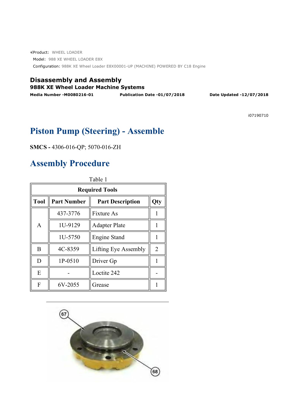
988K XE Wheel Loader E8X00001-UP (MACHINE) POWERED BY C18 Engine(M... 1/12 Product: WHEEL LOADER Model: 988 XE WHEEL LOADER E8X Configuration: 988K XE Wheel Loader E8X00001-UP (MACHINE) POWERED BY C18 Engine Disassembly and Assembly 988K XE Wheel Loader Machine Systems Media Number -M0080216-01 Publication Date -01/07/2018 Date Updated -12/07/2018 i07190710 Piston Pump (Steering) - Assemble SMCS - 4306-016-QP; 5070-016-ZH Assembly Procedure Table 1 Required Tools Tool Part Number Part Description Qty 437-3776 Fixture As 1 A 1U-9129 Adapter Plate 1 1U-5750 Engine Stand 1 B 4C-8359 Lifting Eye Assembly 2 D 1P-0510 Driver Gp 1 E - Loctite 242 - F 6V-2055 Grease 1 https://127.0.0.1/sisweb/sisweb/techdoc/techdoc_print_page.jsp?returnurl=/sis... 2021/12/7
988K XE Wheel Loader E8X00001-UP (MACHINE) POWERED BY C18 Engine(M... 2/12 Illustration 1 g06248518 1. Install O-ring seal (68) into cover (67). Illustration 2 g06248513 2. Install cover (67) and bolts (66). Tighten bolts (66) to a torque of 28 7 N m (248 62 lb in). Install plug (65) and the O-ring seal. Install plug (64) and the O-ring seal. Illustration 3 g06248859 3. Install bearing (63) and retaining ring (62) onto shaft assembly (61). https://127.0.0.1/sisweb/sisweb/techdoc/techdoc_print_page.jsp?returnurl=/sis... 2021/12/7
988K XE Wheel Loader E8X00001-UP (MACHINE) POWERED BY C18 Engine(M... 3/12 Illustration 4 g06248509 4. Use a soft faced hammer to install shaft assembly (61) into housing (43). Illustration 5 g06249254 Illustration 6 g06248624 5. Install O-ring seals (60), O-ring seal (59) into seal carrier (57). Use Tooling (D) to install lip seals (58) into seal carrier (57). https://127.0.0.1/sisweb/sisweb/techdoc/techdoc_print_page.jsp?returnurl=/sis... 2021/12/7
https://www.ebooklibonline.com Hello dear friend! Thank you very much for reading. Enter the link into your browser. The full manual is available for immediate download. https://www.ebooklibonline.com
988K XE Wheel Loader E8X00001-UP (MACHINE) POWERED BY C18 Engine(M... 4/12 Illustration 7 g06248862 6. Apply Tooling (E) to bolts (56). 7. Install seal carrier (57) and bolts (56) onto the pump housing. Tighten bolts (56) to a torque of 28 7 N m (248 62 lb in). Illustration 8 g06248472 8. Install bearing cradles (55) into housing (43). Illustration 9 g06248297 https://127.0.0.1/sisweb/sisweb/techdoc/techdoc_print_page.jsp?returnurl=/sis... 2021/12/7
988K XE Wheel Loader E8X00001-UP (MACHINE) POWERED BY C18 Engine(M... 5/12 9. Install actuators (52), retainers (54), and bolts (53) onto swashplate (50). Tighten bolts (53) to a torque of 12 1 N m (106 9 lb in). Illustration 10 g06248295 10. Install bearing assemblies (51) onto swashplate (50). Illustration 11 g06248290 11. Install swashplate (50) into housing (43). Illustration 12 g06249303 12. Install shims (48) and spring assembly (49) onto barrel (46). https://127.0.0.1/sisweb/sisweb/techdoc/techdoc_print_page.jsp?returnurl=/sis... 2021/12/7
988K XE Wheel Loader E8X00001-UP (MACHINE) POWERED BY C18 Engine(M... 6/12 Illustration 13 g06248271 13. Install hold down ball (47) onto barrel (46). Illustration 14 g06248259 14. Install retainer (45) and pistons (44) onto barrel (46). Illustration 15 g06248257 15. Install rotating group (42) into housing (43). 16. Install O-ring seal (41) into housing (43). Install control actuator (38), spring (40), and bias actuator (39) into housing (43). https://127.0.0.1/sisweb/sisweb/techdoc/techdoc_print_page.jsp?returnurl=/sis... 2021/12/7
988K XE Wheel Loader E8X00001-UP (MACHINE) POWERED BY C18 Engine(M... 7/12 Illustration 16 g06249041 Illustration 17 g06248928 17. Install set screw (37A) and (37B) into head assembly (30). Install set screw (37A) to a depth of 14.3 0.2 mm (0.563 0.008 inch). Install set screw (37B) to a depth of 18 mm (0.71 inch). Install nuts (36). Tighten nuts (36) to a torque of 190 15 N m (140 11 lb ft). Illustration 18 g06248247 18. Install plug (35) and the O-ring seal into head assembly (30). Install plug (34) and the O- ring seal into head assembly (30). https://127.0.0.1/sisweb/sisweb/techdoc/techdoc_print_page.jsp?returnurl=/sis... 2021/12/7
988K XE Wheel Loader E8X00001-UP (MACHINE) POWERED BY C18 Engine(M... 8/12 Illustration 19 g06248187 19. Install plug (33) and the O-ring seal into head assembly (30). Illustration 20 g06248182 20. Install port plate (32) into head assembly (30). Illustration 21 g06248163 https://127.0.0.1/sisweb/sisweb/techdoc/techdoc_print_page.jsp?returnurl=/sis... 2021/12/7
988K XE Wheel Loader E8X00001-UP (MACHINE) POWERED BY C18 Engine(M... 9/12 Illustration 22 g06248159 Improper assembly of parts that are spring loaded can cause bodily injury. To prevent possible injury, follow the established assembly procedure and wear protective equipment. 21. Attach Tooling (B) and a suitable lifting device to head assembly (30). The weight of head assembly (30) is approximately 26 kg (57 lb). Install head assembly (30) onto the pump housing. Install bolts (31). Tighten bolts (31) to a torque of 460 60 N m (339 44 lb ft). Illustration 23 g06248639 22. Install orifice (27) into pump control (7). Install O-ring seal (28) and plug (29) into pump control (7). https://127.0.0.1/sisweb/sisweb/techdoc/techdoc_print_page.jsp?returnurl=/sis... 2021/12/7
988K XE Wheel Loader E8X00001-UP (MACHINE) POWERED BY C18 Engine(... 10/12 Illustration 24 g06248636 Improper assembly of parts that are spring loaded can cause bodily injury. To prevent possible injury, follow the established assembly procedure and wear protective equipment. 23. Install retainer (21), spring (22), spring (23), retainer (24), O-ring seal (25), and adapter (26) into pump control (7). 24. Install retainer (15), spring (16), spring (17), retainer (18), O-ring seal (19), and adapter (20) into pump control (7). Illustration 25 g06248634 25. Install spool (14), O-ring seal (13), and plug (12) into pump control (7). Install spool (10), O -ring seal (9), and plug (8) into pump control (7). Install O-ring seals (11) into pump control (7). https://127.0.0.1/sisweb/sisweb/techdoc/techdoc_print_page.jsp?returnurl=/sis... 2021/12/7
988K XE Wheel Loader E8X00001-UP (MACHINE) POWERED BY C18 Engine(... 11/12 Illustration 26 g06248097 26. Install pump control (7) and bolts (6). Tighten bolts (6) to a torque of 12 3 N m (106 27 lb in). Illustration 27 g06248082 27. Install O-ring seal (5) onto flange (4). Illustration 28 g06248079 28. Apply Tooling (E) to bolts (3). Install flange (4) and bolts (3). https://127.0.0.1/sisweb/sisweb/techdoc/techdoc_print_page.jsp?returnurl=/sis... 2021/12/7
988K XE Wheel Loader E8X00001-UP (MACHINE) POWERED BY C18 Engine(... 12/12 Illustration 29 g06248087 29. Install coupler (2) and O-ring seal (1) into the flange. Remove the pump from Tooling (A) or suitable fixture. End By: a. Install the steering pump. https://127.0.0.1/sisweb/sisweb/techdoc/techdoc_print_page.jsp?returnurl=/sis... 2021/12/7
988K XE Wheel Loader E8X00001-UP (MACHINE) POWERED BY C18 Engine(M... 1/1 Product: WHEEL LOADER Model: 988 XE WHEEL LOADER E8X Configuration: 988K XE Wheel Loader E8X00001-UP (MACHINE) POWERED BY C18 Engine Disassembly and Assembly 988K XE Wheel Loader Machine Systems Media Number -M0080216-01 Publication Date -01/07/2018 Date Updated -12/07/2018 i05431732 Gear Pump (Secondary Steering) - Remove and Install SMCS - 4324-010-GT; 4324-010; 5073-010-SST; 5073-010 Removal Procedure Illustration 1 g03428022 1. Disconnect hose assemblies (1). Remove bolts (3). Use two people to remove gear pump (2). Installation Procedure 1. Install gear pump (2) in the reverse order of removal. https://127.0.0.1/sisweb/sisweb/techdoc/techdoc_print_page.jsp?returnurl=/sis... 2021/12/7
988K XE Wheel Loader E8X00001-UP (MACHINE) POWERED BY C18 Engine(M... 1/7 Product: WHEEL LOADER Model: 988 XE WHEEL LOADER E8X Configuration: 988K XE Wheel Loader E8X00001-UP (MACHINE) POWERED BY C18 Engine Disassembly and Assembly 988K XE Wheel Loader Machine Systems Media Number -M0080216-01 Publication Date -01/07/2018 Date Updated -12/07/2018 i05436054 Gear Pump (Secondary Steering) - Disassemble SMCS - 4324-015-GT; 5073-015-SST Disassembly Procedure Start By: a. Remove the secondary steering pump. 1. Put alignment marks on the secondary steering pump for assembly purposes. Illustration 1 g03430645 https://127.0.0.1/sisweb/sisweb/techdoc/techdoc_print_page.jsp?returnurl=/sis... 2021/12/7
988K XE Wheel Loader E8X00001-UP (MACHINE) POWERED BY C18 Engine(M... 2/7 Illustration 2 g03430650 Personal injury can result from being struck by parts propelled by a released spring force. Make sure to wear all necessary protective equipment. Follow the recommended procedure and use all recommended tooling to release the spring force. 2. Remove bolts (1). Remove body (3) and spacer (2). Illustration 3 g03430651 https://127.0.0.1/sisweb/sisweb/techdoc/techdoc_print_page.jsp?returnurl=/sis... 2021/12/7
988K XE Wheel Loader E8X00001-UP (MACHINE) POWERED BY C18 Engine(M... 3/7 Illustration 4 g03430657 3. Remove O-ring seals (4). Remove pistons (6) and springs (5) from body (3). Illustration 5 g03430687 Illustration 6 g03430688 4. Remove O-ring seals (9), pistons (8) and springs (10) from body (7). https://127.0.0.1/sisweb/sisweb/techdoc/techdoc_print_page.jsp?returnurl=/sis... 2021/12/7
988K XE Wheel Loader E8X00001-UP (MACHINE) POWERED BY C18 Engine(M... 4/7 Illustration 7 g03430690 Illustration 8 g03430692 5. Remove the bolts (11) that hold flange assembly (12) to pump body (7). Remove flange assembly (12) from pump body (7). Illustration 9 g03430693 6. Remove lip seals (13) from flange assembly (12). https://127.0.0.1/sisweb/sisweb/techdoc/techdoc_print_page.jsp?returnurl=/sis... 2021/12/7
988K XE Wheel Loader E8X00001-UP (MACHINE) POWERED BY C18 Engine(M... 5/7 Illustration 10 g03430694 7. Remove O-ring seal (14) and O-ring seals (15) from flange assembly (12). Illustration 11 g03430695 8. Remove seal assembly (16) and retaining plates (17). Illustration 12 g03430696 9. Remove front pressure plate (18). https://127.0.0.1/sisweb/sisweb/techdoc/techdoc_print_page.jsp?returnurl=/sis... 2021/12/7
988K XE Wheel Loader E8X00001-UP (MACHINE) POWERED BY C18 Engine(M... 6/7 Illustration 13 g03430697 10. Remove gear assemblies (19) and (20). Illustration 14 g03430698 11. Remove rear pressure plate (21). Illustration 15 g03430699 12. Remove seals (22), seal assembly (23), and retaining plates (24). https://127.0.0.1/sisweb/sisweb/techdoc/techdoc_print_page.jsp?returnurl=/sis... 2021/12/7
988K XE Wheel Loader E8X00001-UP (MACHINE) POWERED BY C18 Engine(M... 1/6 Product: WHEEL LOADER Model: 988 XE WHEEL LOADER E8X Configuration: 988K XE Wheel Loader E8X00001-UP (MACHINE) POWERED BY C18 Engine Disassembly and Assembly 988K XE Wheel Loader Machine Systems Media Number -M0080216-01 Publication Date -01/07/2018 Date Updated -12/07/2018 i05436056 Gear Pump (Secondary Steering) - Assemble SMCS - 4324-016-GT; 5073-016-SST Specifications Illustration 1 g03192956 Table 1 https://127.0.0.1/sisweb/sisweb/techdoc/techdoc_print_page.jsp?returnurl=/sis... 2021/12/7
988K XE Wheel Loader E8X00001-UP (MACHINE) POWERED BY C18 Engine(M... 2/6 Specification for 150-7585 Gear Pump Gp Item Qty Part Specification Description - - - Displacement per revolution is 83 cc (5.1 cubic inch). 1 8 0S-1595 Bolt Torque to 115 7 N m (85 5 lb ft). 2 6 1B-2886 Bolt Torque to 115 7 N m (85 5 lb ft). 3 1 142-2137 Plug Torque to 24 3 N m (212 27 lb in). 4 1 9S-8005 O-Ring Plug Torque to 284 40 N m (209 30 lb ft). Assembly Procedure Table 2 Required Tools Tool Part Number Part Description Qty A 1P-0510 Driver Group 1 Illustration 2 g03431023 Note: Install the corners of the seals toward the rear of the pump body. Install the brass face of the pressure plate toward the gears. 1. Install seals (22), seal assembly (23), retaining plates (24) and rear pressure plate (21). https://127.0.0.1/sisweb/sisweb/techdoc/techdoc_print_page.jsp?returnurl=/sis... 2021/12/7
988K XE Wheel Loader E8X00001-UP (MACHINE) POWERED BY C18 Engine(M... 3/6 Illustration 3 g03430697 2. Install gear assemblies (19) and (20). Illustration 4 g03430696 Illustration 5 g03430695 Note: Install the brass face of the pressure plate toward the gears. Install the corners of the seals toward the front of the pump body. 3. Install front pressure plate (18), retaining plates (17) and seal assembly (16). https://127.0.0.1/sisweb/sisweb/techdoc/techdoc_print_page.jsp?returnurl=/sis... 2021/12/7
Suggest: For more complete manuals. Please go to the home page. https://www.ebooklibonline.com If the above button click is invalid. Please download this document first, and then click the above link to download the complete manual. Thank you so much for reading
988K XE Wheel Loader E8X00001-UP (MACHINE) POWERED BY C18 Engine(M... 4/6 Illustration 6 g03430694 4. Install seals (15) and O-ring seal (14) on flange assembly (12). Illustration 7 g03430693 Note: Install the back of each lip seal against the back of the other lip seal. 5. Use Tooling (A) in order to install lip seals (13) in flange assembly (12). Illustration 8 g03430692 https://127.0.0.1/sisweb/sisweb/techdoc/techdoc_print_page.jsp?returnurl=/sis... 2021/12/7
988K XE Wheel Loader E8X00001-UP (MACHINE) POWERED BY C18 Engine(M... 5/6 Illustration 9 g03430690 6. Install flange assembly (12) and the bolts (11) that hold flange assembly (12) to pump body (7). Tighten bolts (11) to a torque of 115 7 N m (85 5 lb ft). 7. Turn the shaft of the pump in order to ensure that the shaft turns freely. The shaft should not bind in any direction. Illustration 10 g03430687 8. Install O-ring seals (9), pistons (8) and springs (10) on body (7). Illustration 11 g03430651 9. Install O-ring seals (4), pistons (6) and springs (5) on body (3). https://127.0.0.1/sisweb/sisweb/techdoc/techdoc_print_page.jsp?returnurl=/sis... 2021/12/7
https://www.ebooklibonline.com Hello dear friend! Thank you very much for reading. Enter the link into your browser. The full manual is available for immediate download. https://www.ebooklibonline.com
 POWERED BY C18")
 POWERED BY C18")
 POWERED BY C18")

 POWERED BY C18")
 POWERED BY C18")
 POWERED BY C18")
 POWERED BY C18")
 POWERED BY C18")
 POWERED BY C18")
 POWERED BY C18")
 POWERED BY C18")
 POWERED BY C18")
 POWERED BY C18")
 POWERED BY C18")
 POWERED BY C18")
 POWERED BY C18")
 POWERED BY C18")
 POWERED BY C18")
 POWERED BY C18")
 POWERED BY C18")
 POWERED BY C18")
 POWERED BY C18")

 POWERED BY C18")
 POWERED BY C18")