Caterpillar Cat 3512B Industrial Engine (Prefix BRC) Service Repair Manual Instant Download (BRC00001 and up)
Please open the website below to get the complete manualnn//

Download Presentation

Please find below an Image/Link to download the presentation.
The content on the website is provided AS IS for your information and personal use only. It may not be sold, licensed, or shared on other websites without obtaining consent from the author. Download presentation by click this link. If you encounter any issues during the download, it is possible that the publisher has removed the file from their server.
E N D
Presentation Transcript
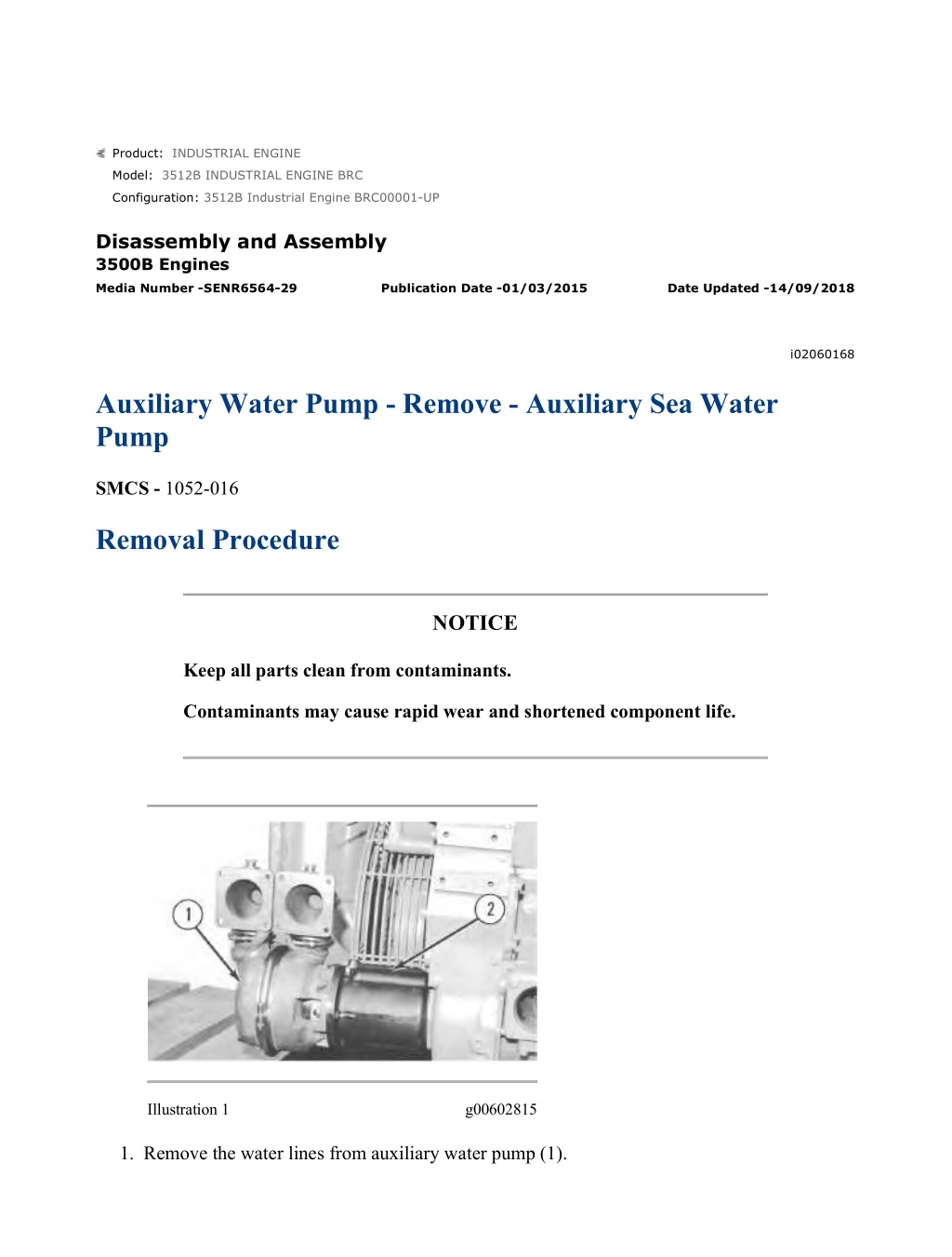
w 1/2(W) Product: INDUSTRIAL ENGINE Model: 3512B INDUSTRIAL ENGINE BRC Configuration: 3512B Industrial Engine BRC00001-UP Disassembly and Assembly 3500B Engines Media Number -SENR6564-29 Publication Date -01/03/2015 Date Updated -14/09/2018 i02060168 Auxiliary Water Pump - Remove - Auxiliary Sea Water Pump SMCS - 1052-016 Removal Procedure NOTICE Keep all parts clean from contaminants. Contaminants may cause rapid wear and shortened component life. Illustration 1 g00602815 1. Remove the water lines from auxiliary water pump (1). https://127.0.0.1/sisweb/sisweb/techdoc/techdoc_print_page.jsp?returnurl=/sisweb/siswe... 2022/5/4
w 2/2(W) 2. Attach a suitable lifting device to auxiliary water pump (1). The weight of the auxiliary water pump is approximately 59 kg (130 lb). 3. Remove the nuts and bolts that fasten auxiliary water pump (1) to housing (2). Remove auxiliary water pump (1). Illustration 2 g00602816 4. Remove bolts and washers (3) in order to remove housing (2). If necessary, remove the bearing from the housing. Illustration 3 g00602821 5. Remove the bolts and remove gear (4) from the accessory drive shaft. https://127.0.0.1/sisweb/sisweb/techdoc/techdoc_print_page.jsp?returnurl=/sisweb/siswe... 2022/5/4
w 1/10(W) Product: INDUSTRIAL ENGINE Model: 3512B INDUSTRIAL ENGINE BRC Configuration: 3512B Industrial Engine BRC00001-UP Disassembly and Assembly 3500B Engines Media Number -SENR6564-29 Publication Date -01/03/2015 Date Updated -14/09/2018 i02060956 Auxiliary Water Pump - Disassemble - Auxiliary Sea Water Pump SMCS - 1052-016 Disassembly Procedure Table 1 Required Tools Tool Part Number Part Description Qty 1P-2320 Combination Puller 1 A 8B-7560 Step Plate 1 8S-2264 Puller Group 1 5/16 inch Bolt 18 NC 76.2 mm (3 inch) length B - 2 4B-5270 Washer (5/16 inch) 2 C 136-1452 Retaining Ring Pliers As 1 D 152-7159 Socket As (Water Pump Shaft) 1 E 1U-7600 Slide Hammer Puller 1 F 1P-0074 Slide Hammer Puller 1 Start By: a. Remove the auxiliary water pump. Refer to Disassembly and Assembly, "Auxiliary Water Pump - Remove". https://127.0.0.1/sisweb/sisweb/techdoc/techdoc_print_page.jsp?returnurl=/sisweb/siswe... 2022/5/4
https://www.ebooklibonline.com Hello dear friend! Thank you very much for reading. Enter the link into your browser. The full manual is available for immediate download. https://www.ebooklibonline.com
w 2/10(W) NOTICE Keep all parts clean from contaminants. Contaminants may cause rapid wear and shortened component life. Illustration 1 g00603001 Illustration 2 g00603003 1. Loosen bolt (2) by approximately 3.0 mm (0.12 inch). Use Tooling (A) in order to pull gear (1) from the shaft. Remove Tooling (A), bolt (2), the washer, and gear (1) from the end of the shaft. https://127.0.0.1/sisweb/sisweb/techdoc/techdoc_print_page.jsp?returnurl=/sisweb/siswe... 2022/5/4
w 3/10(W) Illustration 3 g00690875 2. Remove clamp (3). Illustration 4 g00603007 3. Remove body (4). Remove port plate (5) from the body. Note: Be careful not to damage the threads of the nut and/or the shaft when you remove the cotter pin. Be sure that all of the cotter pin is completely removed before you remove the nut. Illustration 5 g00690890 https://127.0.0.1/sisweb/sisweb/techdoc/techdoc_print_page.jsp?returnurl=/sisweb/siswe... 2022/5/4
w 4/10(W) 4. Remove the cotter pin. Remove nut (6) and the washer from the shaft. Illustration 6 g00603009 5. Use Tooling (B) in order to remove impeller (7) from the shaft. Illustration 7 g01058029 6. Remove key (8A). Remove shims (8), O-ring seal (9), and ring (10). Illustration 8 g00603011 Note: It may be necessary to clean the inside of the body before the port plate can be removed. https://127.0.0.1/sisweb/sisweb/techdoc/techdoc_print_page.jsp?returnurl=/sisweb/siswe... 2022/5/4
w 5/10(W) 7. Remove port plate (11) and spacer (12) from the drive housing. Note: The ceramic seal has two sections. One section is stationary and one section rotates. Do not remove the ceramic seal unless it is necessary. The ceramic seal can be easily damaged. 8. Lubricate the shaft and the rotating section of ceramic seal (13) with a solution of water and five percent soap. Carefully pry the rotating section of the seal away from the drive housing. Remove the rotating section of the seal from the shaft. Illustration 9 g00603013 9. Remove bolts (14) that hold drive housing (15) to bearing housing (16). Separate the drive housing from the bearing housing. Illustration 10 g00690951 10. Use a suitable press in order to remove the stationary section of the ceramic seal from drive housing (15). https://127.0.0.1/sisweb/sisweb/techdoc/techdoc_print_page.jsp?returnurl=/sisweb/siswe... 2022/5/4
w 6/10(W) Illustration 11 g00690988 11. Use an allen wrench to loosen the screws that hold ring (17) to the shaft. Remove the ring. Illustration 12 g01057040 12. Remove O-ring seal (19) and collar (18). Illustration 13 g01057042 13. Place the bearing housing in a vise. Use Tooling (C) in order to remove retaining ring (20). NOTICE https://127.0.0.1/sisweb/sisweb/techdoc/techdoc_print_page.jsp?returnurl=/sisweb/siswe... 2022/5/4
w 7/10(W) Do not allow the shaft to fall when the shaft is removed from the bearing housing. Illustration 14 g01057043 14. Place bearing housing (16) and shaft (21) in a press. Orient the impeller end of the shaft in the upward position. Press the shaft out of the bearing housing. Illustration 15 g01057045 15. Place shaft (21) in a vise. Orient the driven end of the shaft in the upward position. Pry the tab of lock ring (23) out of the slot in nut (22). https://127.0.0.1/sisweb/sisweb/techdoc/techdoc_print_page.jsp?returnurl=/sisweb/siswe... 2022/5/4
w 8/10(W) Illustration 16 g01057048 Illustration 17 g01057051 16. Use Tooling (D) in order to remove nut (22) from shaft (21). Remove lock ring (23) and spacer (24). Illustration 18 g01057054 17. Place shaft (21) in a suitable press. Press the shaft out of bearing (25). Illustration 19 g01057055 https://127.0.0.1/sisweb/sisweb/techdoc/techdoc_print_page.jsp?returnurl=/sisweb/siswe... 2022/5/4
w 9/10(W) 18. Use Tooling (E) in order to remove oil seal (26) from bearing housing (16). Illustration 20 g01057058 19. Use Tooling (C) in order to remove retaining ring (27) from bearing housing (16). 20. Remove bearing (28) from the bearing housing. Illustration 21 g01057060 Illustration 22 g01057062 21. Use Tooling (F) in order to remove bearing race (29) from the bearing housing. https://127.0.0.1/sisweb/sisweb/techdoc/techdoc_print_page.jsp?returnurl=/sisweb/siswe... 2022/5/4
w 1/15(W) Product: INDUSTRIAL ENGINE Model: 3512B INDUSTRIAL ENGINE BRC Configuration: 3512B Industrial Engine BRC00001-UP Disassembly and Assembly 3500B Engines Media Number -SENR6564-29 Publication Date -01/03/2015 Date Updated -14/09/2018 i03237626 Auxiliary Water Pump - Disassemble - Auxiliary Pump (Type 2) SMCS - 1052-016 Disassembly Procedure Table 1 Required Tools Tool Part Number Part Description Qty A 242-9955 Puller (Two Jaw) 1 B 193-8094 Spline Socket 1 C 1P-0510 Driver Gp 1 D 5P-4758 Retaining Ring Pliers As 1 E 280-2059 Spanner Wrench Assembly 1 F 8T-0276 Bolt 2 G 8H-0663 Bearing Puller Gp 1 Start By: a. Remove the auxiliary water pump. Refer to Disassembly and Assembly, "Auxiliary Water Pump - Remove". NOTICE Keep all parts clean from contaminants. Contaminants may cause rapid wear and shortened component life. https://127.0.0.1/sisweb/sisweb/techdoc/techdoc_print_page.jsp?returnurl=/sisweb/siswe... 2022/5/4
w 2/15(W) Disassemble the Check Valve Note: If the hose assembly is leaking, the entire hose assembly must be replaced. Illustration 1 g01644713 1. Remove hose assembly (1), check valve (2), and the gasket from the auxiliary water pump. https://127.0.0.1/sisweb/sisweb/techdoc/techdoc_print_page.jsp?returnurl=/sisweb/siswe... 2022/5/4
w 3/15(W) Illustration 2 g01644824 Personal injury can result from parts and/or covers under spring pressure. Spring force will be released when covers are removed. Be prepared to hold spring loaded covers as the bolts are loosened. 2. Use Tooling (D) in order to remove retainer (3) from the body of check valve (2). 3. Remove spring (4) and disc (5) from the body of check valve (2). Disassemble the Pump https://127.0.0.1/sisweb/sisweb/techdoc/techdoc_print_page.jsp?returnurl=/sisweb/siswe... 2022/5/4
w 4/15(W) Illustration 3 g01645413 1. Remove bolts (6) and cover (7). Remove O-ring seal (8) from cover (7). Illustration 4 g01645415 2. Remove port plate (9). https://127.0.0.1/sisweb/sisweb/techdoc/techdoc_print_page.jsp?returnurl=/sisweb/siswe... 2022/5/4
w 5/15(W) Illustration 5 g01645633 3. Use Tooling (B) to hold the end of the drive shaft. Remove bolt (10), thrust washer (11), and the O-ring seal. Illustration 6 g01645634 Note: Note the orientation of the locking rings during removal. https://127.0.0.1/sisweb/sisweb/techdoc/techdoc_print_page.jsp?returnurl=/sisweb/siswe... 2022/5/4
w 6/15(W) 4. Position the auxiliary water pump in a vertical position on suitable cribbing. Ensure that the shaft assembly is supported. Use Tooling (C) and a suitable hammer to tap impeller (13). This will release the taper on locking rings (12). Remove lock rings (12), impeller (13), ring (14), O-ring seal (15), and port plate (16). Illustration 7 g01645635 5. Remove bolts (17). Use bolts (17) as forcing bolts in order to remove body (18). Remove O- ring seal (19) from body (18). https://127.0.0.1/sisweb/sisweb/techdoc/techdoc_print_page.jsp?returnurl=/sisweb/siswe... 2022/5/4
w 7/15(W) Illustration 8 g01646414 6. Use Tooling (A) and Tooling (C) in order to remove impeller (20). https://127.0.0.1/sisweb/sisweb/techdoc/techdoc_print_page.jsp?returnurl=/sisweb/siswe... 2022/5/4
w 8/15(W) Illustration 9 g01646456 7. Remove the rotating segment of seal assembly (21) from the pump body. https://127.0.0.1/sisweb/sisweb/techdoc/techdoc_print_page.jsp?returnurl=/sisweb/siswe... 2022/5/4
w 9/15(W) Illustration 10 g01646457 8. Place the auxiliary water pump in a vertical position on suitable cribbing, as shown. Remove bolts (23) from bearing housing (22). Use Tooling (F) in Holes (24) in order to separate bearing housing (22) from the pump body. https://127.0.0.1/sisweb/sisweb/techdoc/techdoc_print_page.jsp?returnurl=/sisweb/siswe... 2022/5/4
w 10/15(W) Illustration 11 g01721917 9. Use Tooling (C) and a suitable press to remove the stationary segment of seal assembly (21) from the pump body. https://127.0.0.1/sisweb/sisweb/techdoc/techdoc_print_page.jsp?returnurl=/sisweb/siswe... 2022/5/4
Suggest: For more complete manuals. Please go to the home page. https://www.ebooklibonline.com If the above button click is invalid. Please download this document first, and then click the above link to download the complete manual. Thank you so much for reading
w 11/15(W) Illustration 12 g01646635 10. Use Tooling (D) to remove retaining ring (25) from bearing housing (22). https://127.0.0.1/sisweb/sisweb/techdoc/techdoc_print_page.jsp?returnurl=/sisweb/siswe... 2022/5/4
w 12/15(W) Illustration 13 g01646637 11. Remove setscrews (27) from seal collar (28). Use a suitable press to remove shaft assembly (26) from bearing housing (22). Remove shaft assembly (26), seal collar (28), and the O- ring seal. https://127.0.0.1/sisweb/sisweb/techdoc/techdoc_print_page.jsp?returnurl=/sisweb/siswe... 2022/5/4
https://www.ebooklibonline.com Hello dear friend! Thank you very much for reading. Enter the link into your browser. The full manual is available for immediate download. https://www.ebooklibonline.com