Caterpillar Cat 320C LU Excavator (Prefix MAC) Service Repair Manual Instant Download
Please open the website below to get the complete manualnn//

Download Presentation

Please find below an Image/Link to download the presentation.
The content on the website is provided AS IS for your information and personal use only. It may not be sold, licensed, or shared on other websites without obtaining consent from the author. Download presentation by click this link. If you encounter any issues during the download, it is possible that the publisher has removed the file from their server.
E N D
Presentation Transcript
Service Repair Manual Model 320C U and320C LUExcavator
w 1/13(W) Shutdown SIS Previous Screen Product: EXCAVATOR Model: 320C EXCAVATOR MAC Configuration: 320C U & 320C LU Excavators MAC00001-UP (MACHINE) POWERED BY 3066 Engine Disassembly and Assembly 320C Excavator Machine Systems Media Number -RENR3826-16 Publication Date -01/11/2014 Date Updated -30/03/2016 i01982319 Main Hydraulic Pump and Pump Drive Coupling - Remove SMCS - 5070-011-MV; 5234-011-MV Removal Procedure Table 1 Required Tools Tool Part Number Part Description Qty (A) FT-2674 Vacuum Cap 1 (B) 138-7573 Link Bracket 1 (C) 138-7575 Link Bracket 2 NOTICE Keep all parts clean from contaminants. Contamination of the hydraulic system with foreign material will reduce the service life of the hydraulic system components. To prevent contaminants from entering the hydraulic system, always plug or cap the lines, fittings, or hoses as they are disconnected. Cover any disassembled components and clean them properly before assembly. Clean the hydraulic system properly after any major component exchange or especially after a component failure, to remove any contamination. https://127.0.0.1/sisweb/sisweb/techdoc/techdoc_print_page.jsp?returnurl=/sisweb/sisw... 2019/10/3
w 2/13(W) NOTICE Care must be taken to ensure that fluids are contained during performance of inspection, maintenance, testing, adjusting and repair of the product. Be prepared to collect the fluid with suitable containers before opening any compartment or disassembling any component containing fluids. Refer to Special Publication, NENG2500, "Caterpillar Tools and Shop Products Guide" for tools and supplies suitable to collect and contain fluids on Caterpillar products. Dispose of all fluids according to local regulations and mandates. At operating temperature, the hydraulic oil is hot and under pressure. Hot oils can cause burns. To prevent possible personal injury, release the pressure in the implement hydraulic circuit (boom, stick, bucket, and swing), travel circuits, and the hydraulic oil tank at the filler cap before any hydraulic lines or components are disconnected or removed. Remove the filler cap only when the engine is stopped and the filler cap is cool enough to touch. Note: The following procedure has an attachment valve that is mounted next to the main pump. The exact amount of hoses will vary depending on your machine configuration. Remove only the hoses that are necessary to remove the main hydraulic pump. 1. Release the hydraulic system pressure. Reference: Refer to Disassembly and Assembly, "Hydraulic System Pressure - Release" in this manual. Note: A hydraulic oil sample should be obtained before any maintenance is performed in order to establish the system contaminant level. Refer to Fluid Analysis Laboratory Guide, SEBF3116, "Obtaining an Oil Sample for S O S Analysis". Refer to Operation and Maintenance Manual, "Sampling Interval and Location of Sampling Valve" for the correct location. https://127.0.0.1/sisweb/sisweb/techdoc/techdoc_print_page.jsp?returnurl=/sisweb/sisw... 2019/10/3
https://www.ebooklibonline.com Hello dear friend! Thank you very much for reading. Enter the link into your browser. The full manual is available for immediate download. https://www.ebooklibonline.com
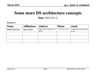
w 3/13(W) Illustration 1 g00688875 2. Remove eight bolts and the washers in order to remove two access covers (1) that are under the main hydraulic pump. 3. Drain the oil from the hydraulic oil tank into a suitable container for storage or disposal. The capacity of the hydraulic oil tank is 120 L (32 US gal). Reference: Refer to Operation and Maintenance, "Hydraulic System Oil - Change" in the service manual. Illustration 2 g01021749 4. Open access door (2) on the right side of the machine. https://127.0.0.1/sisweb/sisweb/techdoc/techdoc_print_page.jsp?returnurl=/sisweb/sisw... 2019/10/3
w 4/13(W) Illustration 3 g00799552 5. Remove two bolts (3) and the washers. 6. Remove cover (4) . Illustration 4 g00689094 7. Place a suitable container for storage or disposal under the main pump suction line. 8. Remove plug (5) from the main pump suction line. 9. Drain the oil from the main pump suction line. https://127.0.0.1/sisweb/sisweb/techdoc/techdoc_print_page.jsp?returnurl=/sisweb/sisw... 2019/10/3
w 5/13(W) Illustration 5 g00690963 10. Remove the cap from the hydraulic tank. Attach Tooling (A) to the hydraulic tank. Note: Hook up the air to Tooling (A) in order to create a vacuum in the hydraulic system. This will minimize the leakage from the tubes and the lines. Note: A small amount of oil will drain from all of the hose assemblies and tube assemblies when the hose assemblies and tube assemblies are disconnected from the main pump. Place a suitable container under the main pump in order to contain the oil. 11. Put identification marks on all of the hose assemblies and on all of the tube assemblies that are connected to the main hydraulic pump for installation purposes. Illustration 6 g00688880 Left side view of the main pump 12. Disconnect electrical connector (6) . 13. Disconnect three hose assemblies (7) from the main pump. https://127.0.0.1/sisweb/sisweb/techdoc/techdoc_print_page.jsp?returnurl=/sisweb/sisw... 2019/10/3
w 6/13(W) Illustration 7 g00689073 14. Disconnect hose assembly (8) from the main pump. Illustration 8 g00689076 15. Disconnect two hose assemblies (9) from the pilot pump. Illustration 9 g00689079 16. Remove hose assembly (10) . https://127.0.0.1/sisweb/sisweb/techdoc/techdoc_print_page.jsp?returnurl=/sisweb/sisw... 2019/10/3
w 7/13(W) 17. Disconnect hose assembly (11) from the main pump. Illustration 10 g00689065 18. Remove two wire ties (12) . 19. Disconnect two electrical connections (13) . 20. Remove bolts (14a), the washers, and the split flanges. 21. Disconnect two hose assemblies (14) from the main pump. Illustration 11 g00688885 Right side view of the main pump 22. Remove bolt (16) and the clip. 23. Remove the wiring harness (17) from the main pump. 24. Loosen, but do not remove bolt (15) . https://127.0.0.1/sisweb/sisweb/techdoc/techdoc_print_page.jsp?returnurl=/sisweb/sisw... 2019/10/3
w 8/13(W) Illustration 12 g00689127 25. Remove bolt (18), the washer, and the nut in order to remove the clamp from the main pump. Illustration 13 g00688884 26. Remove four bolts (20) that hold suction line (19) in position. Illustration 14 g00688891 https://127.0.0.1/sisweb/sisweb/techdoc/techdoc_print_page.jsp?returnurl=/sisweb/sisw... 2019/10/3
w 9/13(W) Bottom shield Illustration 15 g00688895 Top shield Illustration 16 g00688887 The bottom shield and the top shield bolted together. https://127.0.0.1/sisweb/sisweb/techdoc/techdoc_print_page.jsp?returnurl=/sisweb/sisw... 2019/10/3
w 10/13(W) Illustration 17 g00689138 View behind shield (24) 27. Remove three bolts (21) and the washers from the bottom shield. 28. Remove six bolts (26) and the washers from the top shield and the bottom shield. 29. Remove four bolts (25) and the washers from support (23) . 30. Remove support (23) . 31. Loosen but do not remove bolt (27) . 32. Remove bottom shield (22) . 33. Remove two bolts (28) . Illustration 18 g00688888 34. Remove two bolts (29) and the washers. 35. Position the case drain filter and lines out of the way. Note: The case drain filter must be moved in order to remove upper shield (24) . 36. Remove upper shield (24) . Note: The main hydraulic pump must be kept level during removal in order to prevent the binding of the pump drive coupling in the engine flywheel. https://127.0.0.1/sisweb/sisweb/techdoc/techdoc_print_page.jsp?returnurl=/sisweb/sisw... 2019/10/3
w 11/13(W) Illustration 19 g00688900 37. Attach Tooling (B), Tooling (C), and a hoist to the main pump. Note: Attach a ratchet puller to Tooling (B). This will allow you to balance the main pump. Illustration 20 g00688897 38. Remove bolts (30) and the washers that secure the main hydraulic pump to the flywheel housing. 39. Remove the main hydraulic pump (31). The combined weight of the main hydraulic pump and the pump drive coupling is 213 kg (470 lb). https://127.0.0.1/sisweb/sisweb/techdoc/techdoc_print_page.jsp?returnurl=/sisweb/sisw... 2019/10/3
w 12/13(W) Illustration 21 g00689610 40. Remove coupling element (32) . Illustration 22 g00717762 41. Remove four socket head bolts (33) and inserts (34) . Illustration 23 g00689611 42. Remove alignment pins (35) from the flywheel. https://127.0.0.1/sisweb/sisweb/techdoc/techdoc_print_page.jsp?returnurl=/sisweb/sisw... 2019/10/3
w 13/13(W) Illustration 24 g00689612 43. Remove two setscrews (36) . 44. Remove coupling assembly (37) from main hydraulic pump (31) . Illustration 25 g00689613 45. Remove four socket head bolts (39) and four inserts (38) . 46. Remove alignment pins (40) from coupling assembly (37) . Copyright 1993 - 2019 Caterpillar Inc. Thu Oct 3 14:10:03 UTC+0800 2019 All Rights Reserved. Private Network For SIS Licensees. https://127.0.0.1/sisweb/sisweb/techdoc/techdoc_print_page.jsp?returnurl=/sisweb/sisw... 2019/10/3
w 1/12(W) Shutdown SIS Previous Screen Product: EXCAVATOR Model: 320C EXCAVATOR MAC Configuration: 320C U & 320C LU Excavators MAC00001-UP (MACHINE) POWERED BY 3066 Engine Disassembly and Assembly 320C Excavator Machine Systems Media Number -RENR3826-16 Publication Date -01/11/2014 Date Updated -30/03/2016 i01969089 Main Hydraulic Pump and Pump Drive Coupling - Install SMCS - 5070-012-MV; 5234-012-MV Installation Procedure Table 1 Required Tools Tool Part Number Part Description Qty (A) FT-2674 Vacuum Cap 1 (B) 138-7573 Link Bracket 1 (C) 138-7575 Link Bracket 2 (D) 5P-0960 Molybdenum Grease NOTICE Care must be taken to ensure that fluids are contained during performance of inspection, maintenance, testing, adjusting, and repair of the product. Be prepared to collect the fluid with suitable containers before opening any compartment or disassembling any component containing fluids. Refer to Special Publication, NENG2500, "Dealer Service Tool Catalog" for tools and supplies suitable to collect and contain fluids on Cat products. Dispose of all fluids according to local regulations and mandates. https://127.0.0.1/sisweb/sisweb/techdoc/techdoc_print_page.jsp?returnurl=/sisweb/sisw... 2019/10/3
w 2/12(W) Illustration 1 g00689613 1. Install locating pins (40) in coupling assembly (37). 2. Install four inserts (38) and four socket head bolts (39) in coupling assembly (37). 3. Tighten socket head bolts (39) to a torque of 220 10 N m (162 7 lb ft). Note: Make sure that the splined shaft of the main hydraulic pump is clean. Apply Tooling (D) on the splined shaft. Illustration 2 g00689612 4. Install coupling assembly (37) on the splined shaft of main hydraulic pump (31). 5. Install the coupling assembly until the coupling assembly is even with the end of the splined shaft. If necessary, use a soft faced hammer to locate the coupling assembly on the splined shaft. Use a straight edge to be sure that the end of the coupling assembly is even with the end of the splined shaft. 6. Install two setscrews (36). 7. Tighten two setscrews (36) to a torque of 110 10 N m (80 7 lb ft). https://127.0.0.1/sisweb/sisweb/techdoc/techdoc_print_page.jsp?returnurl=/sisweb/sisw... 2019/10/3
w 3/12(W) Illustration 3 g00689611 8. Install alignment pins (35) on the flywheel. Illustration 4 g00717762 9. Install inserts (34) and four socket head bolts (33). 10. Tighten socket head bolts (33) to a torque of 220 10 N m (162 7 lb ft). Illustration 5 g00689610 11. Install coupling element (32). https://127.0.0.1/sisweb/sisweb/techdoc/techdoc_print_page.jsp?returnurl=/sisweb/sisw... 2019/10/3
w 4/12(W) Illustration 6 g00688900 12. Attach Tooling (B), Tooling (C), and a hoist to the main pump. The combined weight of the main hydraulic pump and the pump drive coupling is 213 kg (470 lb). Note: Attach a ratchet puller to Tooling (B). This will allow you to balance the main pump. Illustration 7 g00688897 13. Carefully, install the main hydraulic pump (31) on the engine flywheel housing. 14. Make sure that the coupling assemblies are in alignment with each other. Push the main hydraulic pump against the flywheel housing. Note: The main hydraulic pump must be kept level during installation in order to prevent the binding of the pump drive coupling in the engine flywheel. 15. Install the washers and bolts (30) that secure the main hydraulic pump to the flywheel housing. 16. Remove Tooling (B) and Tooling (C). https://127.0.0.1/sisweb/sisweb/techdoc/techdoc_print_page.jsp?returnurl=/sisweb/sisw... 2019/10/3
w 5/12(W) Illustration 8 g00688888 17. Position the case drain filter and lines out of the way. Note: The case drain filter must be moved in order to install upper shield (24). Illustration 9 g00688891 Bottom shield 18. Install bottom shield (22). 19. Install the washers and three bolts (21) to the bottom shield. Illustration 10 g00688895 https://127.0.0.1/sisweb/sisweb/techdoc/techdoc_print_page.jsp?returnurl=/sisweb/sisw... 2019/10/3
w 6/12(W) Top shield Illustration 11 g00688887 The bottom shield and the top shield bolted together. 20. Install support (23). 21. Install the washers and four bolts (25). 22. Install upper shield (24). 23. Install the washers and six bolts (26). 24. Tighten bolt (27). Illustration 12 g00689138 View behind shield (24) 25. Install the washers and two bolts (28). 26. Place the case drain filter and the lines into position. 27. Install the washers and two bolts (29). https://127.0.0.1/sisweb/sisweb/techdoc/techdoc_print_page.jsp?returnurl=/sisweb/sisw... 2019/10/3
w 7/12(W) Illustration 13 g00688884 28. Connect suction line (19) to the main hydraulic pump with four bolts (20). Illustration 14 g00689127 29. Install the clamp and the hydraulic hoses to the main pump with the nut, the washer, and the bolt (18). Illustration 15 g00688885 Right side view of the main pump 30. Install the wiring harness (17) to the main pump. https://127.0.0.1/sisweb/sisweb/techdoc/techdoc_print_page.jsp?returnurl=/sisweb/sisw... 2019/10/3
w 8/12(W) 31. Install the clip with bolt (16). 32. Tighten bolt (15). Illustration 16 g00690963 33. Install the cap to the hydraulic tank. Attach Tooling (A) to the hydraulic tank. Note: Hook up the air to Tooling (A) in order to create a vacuum in the hydraulic system. This will minimize the leakage from the tubes and the lines. Illustration 17 g00689065 34. Connect two hose assemblies (14) to the main pump. 35. Install the split flanges, the washers, and bolts (14a) that hold hose assemblies (14) to the main pump. 36. Connect two electrical connections (13). 37. Install two wire ties (12). https://127.0.0.1/sisweb/sisweb/techdoc/techdoc_print_page.jsp?returnurl=/sisweb/sisw... 2019/10/3
Suggest: If the above button click is invalid. Please download this document first, and then click the above link to download the complete manual. Thank you so much for reading
w 9/12(W) Illustration 18 g00689079 38. Connect hose assembly (11) to the main pump. 39. Install hose assembly (10). Illustration 19 g00689076 40. Connect two hose assemblies (9) to the pilot pump. Illustration 20 g00689073 41. Connect hose assembly (8) to the main pump. https://127.0.0.1/sisweb/sisweb/techdoc/techdoc_print_page.jsp?returnurl=/sisweb/sisw... 2019/10/3
https://www.ebooklibonline.com Hello dear friend! Thank you very much for reading. Enter the link into your browser. The full manual is available for immediate download. https://www.ebooklibonline.com