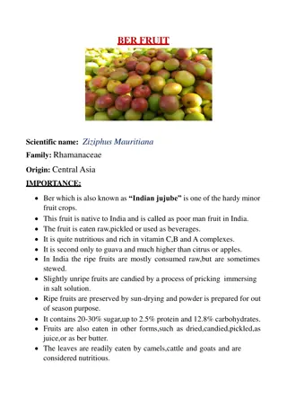
Caterpillar Cat 320C L Excavator (Prefix BER) Service Repair Manual Instant Download
Please open the website below to get the complete manualnn//

Download Presentation

Please find below an Image/Link to download the presentation.
The content on the website is provided AS IS for your information and personal use only. It may not be sold, licensed, or shared on other websites without obtaining consent from the author. Download presentation by click this link. If you encounter any issues during the download, it is possible that the publisher has removed the file from their server.
E N D
Presentation Transcript
Service Repair Manual Model 320C and320C L Excavator
w 1/6(W) Shutdown SIS Previous Screen Product: EXCAVATOR Model: 320C EXCAVATOR BER Configuration: 320C & 320C L Excavators BER00001-UP (MACHINE) POWERED BY 3066 Engine Disassembly and Assembly 320C Excavator Machine Systems Media Number -RENR3826-16 Publication Date -01/11/2014 Date Updated -30/03/2016 i02332586 Blower Motor (Air Conditioner, Heater) - Remove SMCS - 7304-011-BW; 7309-011-BW; 7320-011-BW Removal Procedure Start By: a. Remove the storage box in the cab. Refer to Disassembly and Assembly, "Storage Box and Covers (Cab) - Remove and Install". Illustration 1 g00698935 1. Disconnect harness assembly (1) from the cab air temperature sensor. 2. Disconnect harness assembly (2) from the relays. https://127.0.0.1/sisweb/sisweb/techdoc/techdoc_print_page.jsp?returnurl=/sisweb/sis... 2019/10/16
w 2/6(W) Illustration 2 g00698960 3. Disconnect harness assembly (3) from the damper motor. Illustration 3 g00698971 4. Remove screws (4) and the brackets. Illustration 4 g00698972 5. Remove screws (5) from the air duct. https://127.0.0.1/sisweb/sisweb/techdoc/techdoc_print_page.jsp?returnurl=/sisweb/sis... 2019/10/16
https://www.ebooklibonline.com Hello dear friend! Thank you very much for reading. Enter the link into your browser. The full manual is available for immediate download. https://www.ebooklibonline.com
w 3/6(W) Illustration 5 g00698974 Illustration 6 g00698986 6. Remove bolts (6) that secure blower motor housing (7) to the platform. Illustration 7 g00699002 7. Carefully lift the blower motor housing in order to access harness assembly (8) on the blower motor. 8. Disconnect harness assembly (8) from the blower motor. https://127.0.0.1/sisweb/sisweb/techdoc/techdoc_print_page.jsp?returnurl=/sisweb/sis... 2019/10/16
w 4/6(W) Illustration 8 g00699006 9. Disconnect cable strap (9) from the blower motor housing. 10. Remove the blower motor housing from the machine. Illustration 9 g00699502 11. Remove screw (10) from the support. Illustration 10 g00699125 12. Remove screws (12). 13. Remove air duct (11) from the blower motor. https://127.0.0.1/sisweb/sisweb/techdoc/techdoc_print_page.jsp?returnurl=/sisweb/sis... 2019/10/16
w 5/6(W) Illustration 11 g00699159 14. Remove hose assembly (13) from the blower motor. Illustration 12 g00699149 15. Remove bolts (14). 16. Remove support (15) from the blower motor. Illustration 13 g00699163 17. Remove blower motor (16) from the housing. https://127.0.0.1/sisweb/sisweb/techdoc/techdoc_print_page.jsp?returnurl=/sisweb/sis... 2019/10/16
w 6/6(W) Illustration 14 g00699166 18. Remove seal (17) from the blower motor. Illustration 15 g00699168 19. Remove retaining clip (18). 20. Remove blower wheel (19). Copyright 1993 - 2019 Caterpillar Inc. Wed Oct 16 21:57:37 UTC+0800 2019 All Rights Reserved. Private Network For SIS Licensees. https://127.0.0.1/sisweb/sisweb/techdoc/techdoc_print_page.jsp?returnurl=/sisweb/sis... 2019/10/16
w 1/6(W) Shutdown SIS Previous Screen Product: EXCAVATOR Model: 320C EXCAVATOR BER Configuration: 320C & 320C L Excavators BER00001-UP (MACHINE) POWERED BY 3066 Engine Disassembly and Assembly 320C Excavator Machine Systems Media Number -RENR3826-16 Publication Date -01/11/2014 Date Updated -30/03/2016 i02332984 Blower Motor (Air Conditioner, Heater) - Install SMCS - 7304-012-BW; 7309-012-BW; 7320-012-BW Installation Procedure Illustration 1 g00699168 1. Install blower wheel (19). 2. Install retaining clip (18). https://127.0.0.1/sisweb/sisweb/techdoc/techdoc_print_page.jsp?returnurl=/sisweb/sis... 2019/10/16
w 2/6(W) Illustration 2 g00699166 3. Install seal (17) on the blower motor. Illustration 3 g00699163 Note: Make sure that blower motor (16) is properly aligned in the housing. 4. Install blower motor (16) in the housing. Illustration 4 g00699149 5. Install support (15) on the blower motor and install bolts (14). https://127.0.0.1/sisweb/sisweb/techdoc/techdoc_print_page.jsp?returnurl=/sisweb/sis... 2019/10/16
w 3/6(W) Illustration 5 g00699159 6. Install hose assembly (13) on the blower motor. Illustration 6 g00699125 7. Install air duct (11) on the blower motor and install screws (12). Illustration 7 g00699502 8. Install screw (10) in the support. https://127.0.0.1/sisweb/sisweb/techdoc/techdoc_print_page.jsp?returnurl=/sisweb/sis... 2019/10/16
w 4/6(W) Illustration 8 g00699006 9. Position the blower motor housing in the cab in order to access the harness assembly. 10. Connect cable strap (9) to the blower motor housing. Illustration 9 g00699002 11. Connect harness assembly (8) to the blower motor. Illustration 10 g00698974 https://127.0.0.1/sisweb/sisweb/techdoc/techdoc_print_page.jsp?returnurl=/sisweb/sis... 2019/10/16
w 5/6(W) Illustration 11 g00698986 Note: Make sure that the outlet of the housing is correctly installed in the heating and air conditioning unit. 12. Carefully lift the blower motor housing. Install the blower motor housing. 13. Install bolts (6) that secure blower motor housing (7) to the platform. Illustration 12 g00698971 14. Install the brackets and screws (4). Illustration 13 g00698972 https://127.0.0.1/sisweb/sisweb/techdoc/techdoc_print_page.jsp?returnurl=/sisweb/sis... 2019/10/16
w 6/6(W) 15. Install screws (5) in the air duct. Illustration 14 g00698960 16. Connect harness assembly (3) to the damper motor. Illustration 15 g00698935 17. Connect harness assembly (2) to the relays. 18. Connect harness assembly (1) to the cab air temperature sensor. End By: a. Install the storage box in the cab. Refer to Disassembly and Assembly, "Storage Box and Covers (Cab) - Remove and Install". Copyright 1993 - 2019 Caterpillar Inc. Wed Oct 16 21:58:33 UTC+0800 2019 All Rights Reserved. Private Network For SIS Licensees. https://127.0.0.1/sisweb/sisweb/techdoc/techdoc_print_page.jsp?returnurl=/sisweb/sis... 2019/10/16
w 1/6(W) Shutdown SIS Previous Screen Product: EXCAVATOR Model: 320C EXCAVATOR BER Configuration: 320C & 320C L Excavators BER00001-UP (MACHINE) POWERED BY 3066 Engine Disassembly and Assembly 320C Excavator Machine Systems Media Number -RENR3826-16 Publication Date -01/11/2014 Date Updated -30/03/2016 i02809819 Refrigerant Receiver-Dryer - Remove and Install SMCS - 7322-010 S/N - AMC1-UP S/N - ANB1-UP S/N - BBL1-UP S/N - BCN1-UP S/N - BDC1-UP S/N - BDE1-UP S/N - BEA1-UP S/N - BER1-UP S/N - BPR1-UP S/N - BRX1-UP S/N - CCD1-UP S/N - DBG1-UP S/N - EAG1-UP S/N - EGA1-UP S/N - EGL1-UP S/N - GLA1-UP https://127.0.0.1/sisweb/sisweb/techdoc/techdoc_print_page.jsp?returnurl=/sisweb/sis... 2019/10/16
w 2/6(W) S/N - HKT1-UP S/N - JPL1-UP S/N - JTG1-UP S/N - MAB1-UP S/N - MAC1-UP S/N - PAB1-UP S/N - PAC1-UP S/N - RAW1-UP S/N - SBN1-UP Removal Procedure Note: Cleanliness is an important factor. Before the removal procedure, the exterior of the component should be thoroughly cleaned. This will help to prevent dirt from entering the internal mechanism. Note: Put identification marks on all lines, on all hoses, on all wires, and on all tubes for installation purposes. Plug all lines, hoses, and tubes. This helps to prevent fluid loss and this helps to keep contaminants from entering the system. Personal injury can result from contact with refrigerant. Contact with refrigerant can cause frost bite. Keep face and hands away to help prevent injury. Protective goggles must always be worn when refrigerant lines are opened, even if the gauges indicate the system is empty of refrigerant. Always use precaution when a fitting is removed. Slowly loosen the fitting. If the system is still under pressure, release it slowly in a well ventilated area. Personal injury or death can result from inhaling refrigerant through a lit cigarette. Inhaling air conditioner refrigerant gas through a lit cigarette or other smoking method or inhaling fumes released from a flame contacting air conditioner refrigerant gas, can cause bodily harm or death. Do not smoke when servicing air conditioners or wherever refrigerant gas may be present. https://127.0.0.1/sisweb/sisweb/techdoc/techdoc_print_page.jsp?returnurl=/sisweb/sis... 2019/10/16
w 3/6(W) Use a certified recovery and recycling cart to properly remove the refrigerant from the air conditioning system. 1. Recover the air conditioner refrigerant from the air conditioning system. Refer to Service Manual, SENR5664, "Air Conditioning and Heating Systems with R-134a Refrigerant" for the procedure. Refer to Dealer Service Tool Catalog, NENG2500, "Air Conditioning Tools" for the correct tools. 2. Open the access door that is located behind the cab. Illustration 1 g00700188 3. Remove the bolt and the washer in order to disconnect air conditioner hose assembly (2) from the refrigerant receiver-dryer. 4. Remove the bolt and the washer in order to disconnect air conditioner hose assembly (1) from the refrigerant receiver-dryer. Illustration 2 g00700195 5. Remove O-ring seal (3) from the air conditioner hose assembly. https://127.0.0.1/sisweb/sisweb/techdoc/techdoc_print_page.jsp?returnurl=/sisweb/sis... 2019/10/16
w 4/6(W) 6. Remove O-ring seal (4) from the air conditioner hose assembly. Illustration 3 g00700200 7. Remove bolts (5) and the washers. 8. Remove refrigerant receiver-dryer (6) . Installation Procedure Table 1 Required Tools Tool Part Number Part Description Qty A 1U-6396 O-Ring Assembly Compound B 4C-2964 Refrigerant Leak Detector 1 Illustration 4 g00700200 1. Install refrigerant receiver-dryer (6) in the mounting bracket. https://127.0.0.1/sisweb/sisweb/techdoc/techdoc_print_page.jsp?returnurl=/sisweb/sis... 2019/10/16
w 5/6(W) 2. Install the washers and bolts (5) . Tighten the bolts to a torque of 20 5 N m (14.8 3.7 lb ft). Illustration 5 g00700195 Note: O-ring seals should always be replaced. A used O-ring may not have the same sealing properties as a new O-ring. Use Tooling (A) during the assembly procedure. 3. Install new O-ring seal (3) on the air conditioner hose assembly. 4. Install new O-ring seal (4) on the air conditioner hose assembly. Illustration 6 g00700188 5. Connect air conditioner hose assembly (1) to the refrigerant receiver-dryer. Tighten the bolt to a torque of 5.5 1.5 N m (48.68 13.28 lb in). 6. Connect air conditioner hose assembly (2) to the refrigerant receiver-dryer. Tighten the bolt to a torque of 5.5 1.5 N m (48.68 13.28 lb in). 7. Close the access door. 8. Evacuate the air conditioning system. https://127.0.0.1/sisweb/sisweb/techdoc/techdoc_print_page.jsp?returnurl=/sisweb/sis... 2019/10/16
w 6/6(W) ReferenceRefer to Testing and Adjusting, "Refrigerant System - Evacuate" for the correct procedure. 9. Charge the air conditioning system. The correct charge is 1.1 kg (2.42 lb). ReferenceRefer to Testing and Adjusting, "Refrigerant System - Charge" for the correct procedure. 10. Check the entire air conditioning system for leaks. Note: Use a Tooling (B) to check for leaks. Copyright 1993 - 2019 Caterpillar Inc. Wed Oct 16 21:59:29 UTC+0800 2019 All Rights Reserved. Private Network For SIS Licensees. https://127.0.0.1/sisweb/sisweb/techdoc/techdoc_print_page.jsp?returnurl=/sisweb/sis... 2019/10/16
w 1/15(W) Shutdown SIS Previous Screen Product: EXCAVATOR Model: 320C EXCAVATOR BER Configuration: 320C & 320C L Excavators BER00001-UP (MACHINE) POWERED BY 3066 Engine Disassembly and Assembly 320C Excavator Machine Systems Media Number -RENR3826-16 Publication Date -01/11/2014 Date Updated -30/03/2016 i02333043 Actuator Motor (Air Distributor) - Remove and Install SMCS - 7304-010-MQ; 7309-010-MQ; 7320-010-MQ Removal Procedure Start By: a. Remove the storage box in the cab. Refer to Disassembly and Assembly, "Storage Box and Covers (Cab) - Remove and Install". Removal Procedure of the Actuator Motor for the Air Damper for the Temperature Control Illustration 1 g00699772 1. Disconnect harness assembly (1) from the actuator motor. https://127.0.0.1/sisweb/sisweb/techdoc/techdoc_print_page.jsp?returnurl=/sisweb/sis... 2019/10/16
w 2/15(W) Illustration 2 g00699776 2. Remove screw (2) in order to disconnect linkage (3). Illustration 3 g00699782 3. Remove screws (4) from the actuator motor. 4. Remove actuator motor (5). Illustration 4 g00699790 5. Remove linkage (6) from the actuator motor. https://127.0.0.1/sisweb/sisweb/techdoc/techdoc_print_page.jsp?returnurl=/sisweb/sis... 2019/10/16
w 3/15(W) Removal Procedure of the Actuator Motor for the Front Air Damper Illustration 5 g00699809 1. Disconnect harness assembly (1) from the actuator motor. Illustration 6 g00699811 2. Remove screw (4). Remove the cable strap for the harness assembly. 3. Remove screws (2) from the actuator motor. 4. Remove actuator motor (5). https://127.0.0.1/sisweb/sisweb/techdoc/techdoc_print_page.jsp?returnurl=/sisweb/sis... 2019/10/16
w 4/15(W) Illustration 7 g00699816 5. Remove linkage (3) from the actuator motor. Removal Procedure of the Actuator Motor for the Fresh Air or Recirculated Air Damper Illustration 8 g00699825 1. Disconnect harness assembly (1) from the actuator motor. Illustration 9 g00699828 2. Remove screw (2) from the linkage. https://127.0.0.1/sisweb/sisweb/techdoc/techdoc_print_page.jsp?returnurl=/sisweb/sis... 2019/10/16
Suggest: If the above button click is invalid. Please download this document first, and then click the above link to download the complete manual. Thank you so much for reading
w 5/15(W) Illustration 10 g00699833 The heating and air conditioning unit is removed for photographic purposes. 3. Remove screws (3) from the actuator motor. 4. Remove actuator motor (4). Illustration 11 g00699850 5. Remove linkage (5) from the actuator motor. Removal Procedure of the Actuator Motor for the Air Damper for the Rear Window Defroster https://127.0.0.1/sisweb/sisweb/techdoc/techdoc_print_page.jsp?returnurl=/sisweb/sis... 2019/10/16
https://www.ebooklibonline.com Hello dear friend! Thank you very much for reading. Enter the link into your browser. The full manual is available for immediate download. https://www.ebooklibonline.com