Latest Consensus on UWB Sensing for 802.15.4ab

Project: IEEE P802.15 Working Group for Wireless Personal Area Networks (WPANs)
Project: IEEE P802.15 Working Group for Wireless Personal Area Networks (WPANs)
Submission Title:
Latest Consensus on UWB Sensing for 802.15.4ab
Date Submitted:
May 18, 2023
Authors:
Pooria Pakrooh, Bin Tian, Steve Shellhammer, Koorosh Akhavan (Qualcomm), Xiaohui Peng,
David Xun Yang, Bin Qian, Lei Huang, Rojan Chitrakar, Li Sun (Huawei), Frank Leong, Wolfgang
Küchler, Riku Pirhonen, Bernhard Großwindhager (NXP Semiconductors), Dag Wisland,
Håkon
Hjortland, Kristian Granhaug, Jan Roar Pleym (Novelda), Dries Neirynck (Ultra Radio Ltd),
Claudio da
Silva, Carlos Aldana, Kangjin Yoon (Meta), Billy Verso, Carl Murray, Igor Dotlic, Michael McLaughlin
(Qorvo), Xiliang Luo, Vinod Kristem, Jinjing Jiang (Apple),
Aniruddh
Rao, Mingyu Lee (Samsung),
Li
Ma, Li-Hsiang Sun (MediaTek)
Abstract:
Latest consensus among co-authors on UWB sensing topics for 802.15.4ab
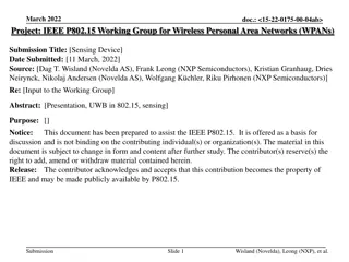
Notice:
This document has been prepared to assist the IEEE P802.15. It is offered as a basis for
discussion and is not binding on the contributing individual(s) or organization(s). The material in this
document is subject to change in form and content after further study. The contributor(s) reserve(s) the
right to add, amend or withdraw material contained herein.
Release:
The contributor acknowledges and accepts that this contribution becomes the property of
IEEE and may be made publicly available by P802.15.
Slide 1
Sensing Pulse Shape
Slide 2
Pakrooh et al. (Qualcomm)
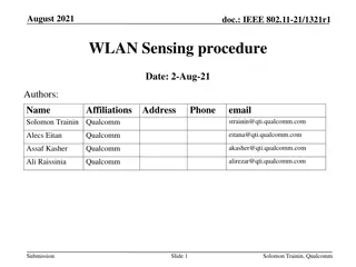
Sensing Packet Format
•
We agree to define the following PPDUs for bi/multi-static sensing.
◦
S
E
N
S
0
:
M
a
n
d
a
t
o
r
y
s
e
n
s
i
n
g
p
a
c
k
e
t
f
o
r
m
a
t
,
S
H
R
+
s
e
n
s
i
n
g
◦
S
E
N
S
1
:
O
p
t
i
o
n
a
l
p
a
c
k
e
t
f
o
r
m
a
t
,
s
e
n
s
i
n
g
+
d
a
t
a
c
o
m
m
◦
S
E
N
S
2
:
O
p
t
i
o
n
a
l
p
a
c
k
e
t
f
o
r
m
a
t
,
d
a
t
a
c
o
m
m
+
s
e
n
s
i
n
g
Slide 3
Pakrooh et al. (Qualcomm)
Arrow shows RMARKER
reference position.
Sensing Sequence and Pulse Pattern
•
We agree on mandatory support of Ipatov sequences of length 91,
as specified in
table 15-7a of 802.15.4z-2020, with spreading factor of L=4 for sensing.
•
A
n
S
D
E
V
m
a
y
o
p
t
i
o
n
a
l
l
y
s
u
p
p
o
r
t
a
d
d
i
t
i
o
n
a
l
m
o
d
e
s
e
n
s
i
n
g
o
n
l
y
f
o
r
S
E
N
S
0
p
a
c
k
e
t
,
w
h
e
r
e
a
l
l
t
h
r
e
e
f
i
e
l
d
s
(
S
Y
N
C
,
S
F
D
,
a
n
d
S
E
N
S
)
u
s
e
t
h
e
s
a
m
e
l
e
n
g
t
h
1
2
7
c
o
d
e
f
r
o
m
T
a
b
l
e
1
5
-
7
o
f
t
h
e
1
5
.
4
s
t
a
n
d
a
r
d
,
w
i
t
h
s
p
r
e
a
d
i
n
g
f
a
c
t
o
r
o
f
L
=
4
.
T
h
i
s
b
r
i
n
g
s
t
h
e
P
R
F
t
o
6
2
.
4
M
H
z
.
o
SYNC PSR and SFD length options in this mode are the same as HPRF mode, as
discussed in slide 10.
Slide 4
Pakrooh et al. (Qualcomm)
Sensing Packet Structure
•
Segments
o
We agree that in the baseline mandatory mode, SENS field has one segment.
o
We agree on optional support for 2, 3 and 4 segments in the SENS field.
•
Gap
o
We agree that SENS field includes silent intervals called “gaps”
•
When multiple segments are used
, we agree to include
gaps between segments.
•
The duration of each gap interval is one SENS symbol.
•
See next slides for figures
•
RMARKER
o
We agree to have one RMARKER for sensing packets. The position of the RMARKER is
at the peak of first pulse after SFD (as per 4z).
Slide 5
Pakrooh et al. (Qualcomm)
Sensing Packet Structure
•
Number of SENS Symbols
o
Each symbol corresponds to one period of SENS sequence with spreading
o
We agree to support 32, 64, 128 (Mandatory) 16, 256, 512 (optional) symbols per
segment for SENS.
o
Sequence selection
•
W
e
a
g
r
e
e
t
h
a
t
b
o
t
h
S
E
N
S
a
n
d
S
Y
N
C
i
n
t
h
e
s
a
m
e
s
e
n
s
i
n
g
p
a
c
k
e
t
s
h
a
l
l
u
s
e
s
a
m
e
I
p
a
t
o
v
c
o
d
e
i
n
d
e
x
.
•
CIR Report
o
For sensing packets SENS0, SENS1 and SENS2, we agree to support one CIR
report per SENS segment per Rx. No CIR report from SYNC field.
o
Sensing CIR report is optionally supported with non-sensing packets (dynamic-data
packet, MMS and SP0-3)
•
The field used for CIR report generation should be agreed during control phase.
Slide 6
Pakrooh et al. (Qualcomm)
SENS0 Packet
•
Support for one segment is mandatory, 2,3 and 4 segments is optional
Slide 7
Pakrooh et al. (Qualcomm)
SENS1 Packet
•
Support for one segment is mandatory, 2,3 and 4 segments is optional
Slide 8
Pakrooh et al. (Qualcomm)
RMARKER
SENS2 Packet
•
Support for one segment is mandatory, 2,3 and 4 segments is optional
Slide 9
Pakrooh et al. (Qualcomm)
Sensing Packet Fields
•
We agree on the following values for SYNC and SFD configs for sensing
packets
o
SYNC PSR:
32, 64 (mandatory), 16, 128, 256 (optional).
o
SFD length: Same as 15.4z, as specified in table 15-7c.
o
For sensing, we agree that fixed PSR is negotiated at higher layers, and the value
does not change from packet to packet.
•
We agree to use 4z PHR, with payload data rates of 1.95, 7.8, 31.2, 62.4
(mandatory), and 124.8Mbps (optional).
o
FEC: We agree on BCC K=7 as the FEC for SNES1 and SENS2 packets.
Slide 10
Pakrooh et al. (Qualcomm)
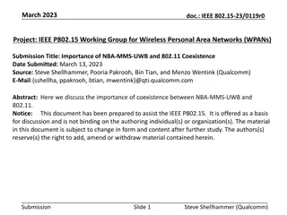
Sensing Report
•
W
e agree to have window-based CIR report, as shown in the figure below.
o
A sensing report bitmap is used to signal the taps present in the CIR report. The bitmap
length is equal to the CIR window length.
•
Additionally, we agree that other processed results may be included in the sensing
report.
◦
F
o
r
m
o
n
o
s
t
a
t
i
c
s
e
n
s
i
n
g
,
o
r
f
o
r
b
i
-
s
t
a
t
i
c
s
e
n
s
i
n
g
w
i
t
h
e
x
t
e
r
n
a
l
s
y
n
c
h
r
o
n
i
z
a
t
i
o
n
,
C
I
R
r
e
p
o
r
t
m
a
y
b
e
o
p
t
i
o
n
a
l
l
y
p
r
o
c
e
s
s
e
d
,
t
o
g
e
n
e
r
a
t
e
r
a
n
g
e
/
v
e
l
o
c
i
t
y
f
o
r
e
a
c
h
o
b
j
e
c
t
.
T
h
e
d
e
f
i
n
i
t
i
o
n
o
f
c
o
m
p
u
t
a
t
i
o
n
m
e
t
h
o
d
i
s
T
B
D
.
◦
Angle of Arrival (AoA) for each object may be reported.
Slide 11
Pakrooh et al. (Qualcomm)
Sensing Report
•
W
e
a
g
r
e
e
o
n
t
h
e
f
o
l
l
o
w
i
n
g
p
a
r
a
m
e
t
e
r
s
f
o
r
t
h
e
w
i
n
d
o
w
-
b
a
s
e
d
C
I
R
r
e
p
o
r
t
.
◦
R
e
f
e
r
e
n
c
e
:
T
h
e
e
a
r
l
i
e
s
t
d
e
t
e
c
t
e
d
t
a
p
c
a
n
b
e
s
p
e
c
i
f
i
e
d
a
s
t
h
e
m
a
n
d
a
t
o
r
i
l
y
s
u
p
p
o
r
t
e
d
r
e
f
e
r
e
n
c
e
f
o
r
t
h
e
C
I
R
r
e
p
o
r
t
.
O
t
h
e
r
r
e
f
e
r
e
n
c
e
o
p
t
i
o
n
s
u
n
d
e
r
c
o
n
s
i
d
e
r
a
t
i
o
n
,
t
o
b
e
s
u
p
p
o
r
t
e
d
o
p
t
i
o
n
a
l
l
y
:
•
Other specific time instances can be specified as reference points (for example via OOB) when there is
external synchronization.
•
T
h
e
s
t
r
o
n
g
e
s
t
d
e
t
e
c
t
e
d
t
a
p
,
i
f
t
h
e
r
e
a
r
e
m
u
l
t
i
p
l
e
e
q
u
a
l
l
y
s
t
r
o
n
g
e
s
t
t
a
p
s
,
t
h
e
n
t
h
e
e
a
r
l
i
e
s
t
o
n
e
i
s
s
e
l
e
c
t
e
d
.
◦
CIR sampling rate: We agreed on OSR=2, to balance reasonable accuracy, complexity and
report overhead. OSR is defined with respect to signal BW.
◦
For frequency stitching, OSR is defined with respect to the aggregated BW.
◦
B
i
t
-
w
i
d
t
h
:
B
i
t
-
w
i
d
t
h
i
s
d
e
f
i
n
e
d
f
o
r
e
n
c
o
d
i
n
g
s
i
g
n
e
d
I
/
Q
v
a
l
u
e
s
e
a
c
h
,
n
o
r
m
a
l
i
z
e
d
p
e
r
R
x
c
h
a
i
n
.
•
16 bits (mandatory), 10, 12 bits, and other values are under consideration as optional values.
Slide 12
Pakrooh et al. (Qualcomm)
Sensing Report
•
W
e
a
g
r
e
e
o
n
t
h
e
f
o
l
l
o
w
i
n
g
p
o
i
n
t
s
f
o
r
t
h
e
w
i
n
d
o
w
-
b
a
s
e
d
C
I
R
r
e
p
o
r
t
.
◦
The CIR report window has configurable duration and position, to cover a large sensing
area.
◦
Further agreements regarding CIR report bitmap
•
Single CIR window with bitmap of a
fixed length
is
specified through OOB means.
•
The bitmap length is negotiated and determined through other means, and it is fixed
during sensing session.
•
In the mandatory mode, initiator proposes the bitmap, based on its sensing area of
interest, from a limited set of bitmap options.
•
Bitmap is fixed during the session and does not change from packet to packet.
•
For the optional modes,
the bitmap can change
from packet to packet.
Slide 13
Pakrooh et al. (Qualcomm)
Modes for Report Bitmap
•
In the mandatory bitmap mode, we agreed that a limited set of reasonable
bitmap options will be defined in the standard. Initiator proposes one bitmap
based on its area of interest. The allowed configs are one or two continuous
strings of 1s within the bitmap length.
o
The SDEVs shall support the mandatory window configurations
No need for
negotiation.
•
In the optional bitmap mode, we agreed that the bitmap can change
from packet
to packet
◦
The responder
reports CIR taps above a threshold, and the associated
bitmap
◦
Initiator determines the threshold value
•
The responder reports taps above a threshold level T (for example, strongest tap
level – T)
•
T is determined by initiator
•
If initiator does not want the CIR report to be thresholded, it specifies a very low
value for T (for example, -100dB).
Slide 14
Mandatory CIR Report Bitmap Configs
Slide 15
Mandatory CIR Report Bitmap Configs
•
Total of 88 bitmap options:
o
One string of all ones for M={32,64,128,256}o
Two strings of equal length L, with gap G
•
M = 64, L = 16, G = {8, 16, 24, 32}
4 cases
•
M = 128, L = 16, G = {40, 48,….,96}
8 cases
•
M = 256, L = 16, G = {104, 112, …., 224}
16 cases
•
M = 128, L = 32, G = {8, 16, …, 64}
8 cases
•
M = 256, L = 32, G = {72, …, 192}
16 cases
•
M = 256, L = 64, G = {8, 16, …,128}
32 cases
Slide 16
Baseline Sensing Report Parameters
Slide 17
Pakrooh et al. (Qualcomm)
Frequency Stitching
•
We agree to adopt frequency stitching across carrier frequencies to improve
sensing link budget and accuracy, as an
optional
feature for mono-static,
bi/multi-static modes.
◦
Consider to limit channels where this option is available to avoid interference with
multiple UWB channels.
◦
For frequency stitching mode, if intra-packet frequency stitching is enabled, extended
gap size between SENS segments will be adopted. The duration of extended gap is
TBD.
Slide 18
Sensing Session
•
A sensing session consists of three phases:
•
Session setup
•
Sensing measurement instance(s)
•
Session termination
Slide 19
Sensing Session Setup
•
S
e
s
s
i
o
n
s
e
t
u
p
:
T
h
e
s
e
s
s
i
o
n
s
e
t
u
p
p
h
a
s
e
c
a
n
b
e
d
o
n
e
O
O
B
,
a
n
d
i
t
c
o
n
s
i
s
t
s
o
f
t
h
e
f
o
l
l
o
w
i
n
g
s
t
e
p
s
1.
Transmission of a sensing session setup request frame by the sensing
initiator to a sensing responder, followed by transmission of an Ack
frame by the responder, and
2.
Transmission of a sensing session setup response by the responder
(followed by an Ack) to the sensing initiator to either
a)
Accept the parameters proposed by the initiator, or
b)
Reject and provide responder’s preferred operational parameters in the
sensing session response frame.
Slide 20
Measurement instance
•
S
e
n
s
i
n
g
m
e
a
s
u
r
e
m
e
n
t
i
n
s
t
a
n
c
e
(
s
)
:
•
Sensing session parameters configured during session setup phase may be
updated during the control phase.
•
A sensing initiator or a sensing responder starts a sensing phase by transmitting
a sensing PPDU type which is agreed upon during the session setup or control
phase.
•
A measurement report phase may follow the sounding PPDU transmission.
Slide 21
Measurement report
•
S
e
n
s
i
n
g
m
e
a
s
u
r
e
m
e
n
t
r
e
p
o
r
t
:
T
h
e
m
e
a
s
u
r
e
m
e
n
t
r
e
p
o
r
t
p
h
a
s
e
i
s
p
e
r
f
o
r
m
e
d
a
f
t
e
r
t
h
e
m
e
a
s
u
r
e
m
e
n
t
p
h
a
s
e
.
F
o
r
t
h
e
c
a
s
e
t
h
a
t
t
h
e
i
n
i
t
i
a
t
o
r
i
s
t
h
e
t
r
a
n
s
m
i
t
t
e
r
,
r
e
s
p
o
n
d
e
r
s
h
a
l
l
p
r
o
v
i
d
e
m
e
a
s
u
r
e
m
e
n
t
r
e
p
o
r
t
t
o
t
h
e
i
n
i
t
i
a
t
o
r
.
T
h
i
s
c
a
n
b
e
s
e
n
t
i
n
-
b
a
n
d
o
r
O
O
B
.
•
When initiator is transmitter, measurement report phase is mandatory.
•
Two types of sensing measurement report are defined
•
MAC Layer Management Entity report: Used to send sensing measurement
results to the application layer of the initiator device.
•
OTA CIR measurement report:
Used to send sensing measurement report from
responder to the initiator.
Slide 22
Round/block/slot structure
•
S
e
n
s
i
n
g
r
o
u
n
d
/
b
l
o
c
k
/
s
l
o
t
s
t
r
u
c
t
u
r
e
:
C
o
m
m
o
n
s
t
r
u
c
t
u
r
e
i
s
u
s
e
d
f
o
r
s
e
n
s
i
n
g
,
r
a
n
g
i
n
g
,
a
n
d
d
a
t
a
c
o
m
m
.
S
e
n
s
i
n
g
r
o
u
n
d
/
b
l
o
c
k
a
n
d
s
l
o
t
s
a
r
e
s
t
r
u
c
t
u
r
e
d
t
h
e
s
a
m
e
a
s
r
a
n
g
i
n
g
,
i
l
l
u
s
t
r
a
t
e
d
i
n
t
h
e
f
i
g
u
r
e
b
e
l
o
w
.
Slide 23
Round/block/slot structure
•
A sensing measurement instance is performed during a sensing
round.
•
First slot (slot0) of each round is used for control phase.
•
One or multiple slots are used for sensing phase. A sensing PPDU is transmitted
during sensing phase.
•
Multiple slots may be used for measurement report phase.
Slide 24
Sensing Scheduling and Control
•
The Scheduling IE defined in DCN 15-23-62/r3 for 15.4ab is used for
scheduling a sensing round.
•
The AC control IE defined in DCN
15-23-61/r1
is used to define
sensing control parameters.
•
The control field of the AC IE includes at least the following parameters
•
Extra field will be added to enable CIR report request for non-sensing packets
(STS 0-3, dynamic data, MMS)
•
The content of each field is expanded in the next slides.
Slide 25
Common Sensing Control
•
Common sensing control field of AC IE includes the following
parameters
0: Transmitter
1: Receiver
0: Monostatic
1: Bi-static
2: Multi-static
3: Proxy
Slide 26
CIR Report and Frequency Stitching Fields
•
Frequency stitching field AC IE
•
CIR Report field of AC IE includes the following parameters
Bitmap mode
0: Initiator sets bitmap from predefined subset of bitmaps
1: Initiator sets bitmap from configs not specified in the defined subset
2: Responder sets bitmap and reports it
Only present if bitmap mode=0
See next slide for sub-window length
(L) and Gap (G)
Only present if
bitmap mode=1
Slide 27
doc.: IEEE 802.15-<15-22-0609-01-04ab>
Page
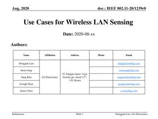
Co-authors from various companies present the latest agreement on ultra-wideband (UWB) sensing topics for the IEEE 802.15.4ab standard. The consensus includes definitions for sensing pulse shape, packet formats for bi/multi-static sensing, and support for specific sequences and patterns in UWB sensing applications. This submission aims to inform and guide future developments in UWB sensing technologies for wireless personal area networks (WPANs).

Download Presentation

Please find below an Image/Link to download the presentation.
The content on the website is provided AS IS for your information and personal use only. It may not be sold, licensed, or shared on other websites without obtaining consent from the author.If you encounter any issues during the download, it is possible that the publisher has removed the file from their server.
You are allowed to download the files provided on this website for personal or commercial use, subject to the condition that they are used lawfully. All files are the property of their respective owners.
The content on the website is provided AS IS for your information and personal use only. It may not be sold, licensed, or shared on other websites without obtaining consent from the author.
E N D
Presentation Transcript
doc.: <15-23-0284-00-04ab> Project: IEEE P802.15 Working Group for Wireless Personal Area Networks (WPANs) Submission Title: Latest Consensus on UWB Sensing for 802.15.4ab Date Submitted: May 18, 2023 Authors: Pooria Pakrooh, Bin Tian, Steve Shellhammer, Koorosh Akhavan (Qualcomm), Xiaohui Peng, David Xun Yang, Bin Qian, Lei Huang, Rojan Chitrakar, Li Sun (Huawei), Frank Leong, Wolfgang K chler, Riku Pirhonen, Bernhard Gro windhager (NXP Semiconductors), Dag Wisland, H kon Hjortland, Kristian Granhaug, Jan Roar Pleym (Novelda), Dries Neirynck (Ultra Radio Ltd), Claudio da Silva, Carlos Aldana, Kangjin Yoon (Meta), Billy Verso, Carl Murray, Igor Dotlic, Michael McLaughlin (Qorvo), Xiliang Luo, Vinod Kristem, Jinjing Jiang (Apple), Aniruddh Rao, Mingyu Lee (Samsung), Li Ma, Li-Hsiang Sun (MediaTek) Abstract: Latest consensus among co-authors on UWB sensing topics for 802.15.4ab Notice: discussion and is not binding on the contributing individual(s) or organization(s). The material in this document is subject to change in form and content after further study. The contributor(s) reserve(s) the right to add, amend or withdraw material contained herein. Release: The contributor acknowledges and accepts that this contribution becomes the property of IEEE and may be made publicly available by P802.15. This document has been prepared to assist the IEEE P802.15. It is offered as a basis for Latest Consensus on UWB Sensing for 802.15.4ab Slide 1
doc.: <15-23-0284-00-04ab> Sensing Pulse Shape We agree on a two-step definition for sensing pulse shape. Time-bounded Kaiser with chips is recommended in 15.4ab as the reference pulse shape for sensing. The value of ?= ?? is TBD. 2 2? ? ?0?? 1 ?(?) = , ? ?/2 ?0?? 0, ? > ?/2 A restrictive sensing time-domain mask and cross-correlation metric , need to be defined in 15.4ab. Details of the requirements are TBD. We agree to use one pulse shape per 4ab packet. Pulse shape does not change in the middle of packet. Sensing pulse shape is used for entire packet in sensing applications. Latest Consensus on UWB Sensing for 802.15.4ab Pakrooh et al. (Qualcomm) Slide 2
doc.: <15-23-0284-00-04ab> Sensing Packet Format We agree to define the following PPDUs for bi/multi-static sensing. SENS0: Mandatory sensing packet format, SHR + sensing SENS1: Optional packet format, sensing + data comm SENS2: Optional packet format, data comm + sensing SENS0 SYNC SFD SENS Mandatory Optional SENS1 SFD Payload SYNC SENS PHR Optional SENS2 PHR SENS Payload SFD SYNC Arrow shows RMARKER reference position. Latest Consensus on UWB Sensing for 802.15.4ab Pakrooh et al. (Qualcomm) Slide 3
doc.: <15-23-0284-00-04ab> Sensing Sequence and Pulse Pattern We agree on mandatory support of Ipatov sequences of length 91, as specified in table 15-7a of 802.15.4z-2020, with spreading factor of L=4 for sensing. An SDEV may optionally support additional mode sensing only for SENS0 packet, where all three fields (SYNC, SFD, and SENS) use the same length 127 code from Table 15-7 of the 15.4 standard, with spreading factor of L=4. This brings the PRF to 62.4MHz. o SYNC PSR and SFD length options in this mode are the same as HPRF mode, as discussed in slide 10. Latest Consensus on UWB Sensing for 802.15.4ab Pakrooh et al. (Qualcomm) Slide 4
doc.: <15-23-0284-00-04ab> Sensing Packet Structure Segments o We agree that in the baseline mandatory mode, SENS field has one segment. o We agree on optional support for 2, 3 and 4 segments in the SENS field. Gap o We agree that SENS field includes silent intervals called gaps When multiple segments are used, we agree to include gaps between segments. The duration of each gap interval is one SENS symbol. See next slides for figures RMARKER o We agree to have one RMARKER for sensing packets. The position of the RMARKER is at the peak of first pulse after SFD (as per 4z). Latest Consensus on UWB Sensing for 802.15.4ab Pakrooh et al. (Qualcomm) Slide 5
doc.: <15-23-0284-00-04ab> Sensing Packet Structure Number of SENS Symbols o Each symbol corresponds to one period of SENS sequence with spreading o We agree to support 32, 64, 128 (Mandatory) 16, 256, 512 (optional) symbols per segment for SENS. o Sequence selection We agree that both SENS and SYNC in the same sensing packet shall use same Ipatov code index. CIR Report o For sensing packets SENS0, SENS1 and SENS2, we agree to support one CIR report per SENS segment per Rx. No CIR report from SYNC field. o Sensing CIR report is optionally supported with non-sensing packets (dynamic-data packet, MMS and SP0-3) The field used for CIR report generation should be agreed during control phase. Latest Consensus on UWB Sensing for 802.15.4ab Pakrooh et al. (Qualcomm) Slide 6
doc.: <15-23-0284-00-04ab> SENS0 Packet Support for one segment is mandatory, 2,3 and 4 segments is optional RMARKER SENS SYNC SFD SENS active SENS active Gap Gap Single segment SENS Two segment SENS Latest Consensus on UWB Sensing for 802.15.4ab Pakrooh et al. (Qualcomm) Slide 7
doc.: <15-23-0284-00-04ab> SENS1 Packet Support for one segment is mandatory, 2,3 and 4 segments is optional RMARKER PHR Payload SENS SYNC SFD Gap Gap SENS active Gap SENS active Single segment SENS Two segment SENS Latest Consensus on UWB Sensing for 802.15.4ab Pakrooh et al. (Qualcomm) Slide 8
doc.: <15-23-0284-00-04ab> SENS2 Packet Support for one segment is mandatory, 2,3 and 4 segments is optional RMARKER Payload PHR SYNC SFD SENS Gap SENS active Gap SENS active Single segment SENS Two segment SENS Latest Consensus on UWB Sensing for 802.15.4ab Pakrooh et al. (Qualcomm) Slide 9
doc.: <15-23-0284-00-04ab> Sensing Packet Fields We agree on the following values for SYNC and SFD configs for sensing packets o SYNC PSR: 32, 64 (mandatory), 16, 128, 256 (optional). o SFD length: Same as 15.4z, as specified in table 15-7c. o For sensing, we agree that fixed PSR is negotiated at higher layers, and the value does not change from packet to packet. We agree to use 4z PHR, with payload data rates of 1.95, 7.8, 31.2, 62.4 (mandatory), and 124.8Mbps (optional). o FEC: We agree on BCC K=7 as the FEC for SNES1 and SENS2 packets. Latest Consensus on UWB Sensing for 802.15.4ab Pakrooh et al. (Qualcomm) Slide 10
doc.: <15-23-0284-00-04ab> Sensing Report We agree to have window-based CIR report, as shown in the figure below. A sensing report bitmap is used to signal the taps present in the CIR report. The bitmap length is equal to the CIR window length. o Additionally, we agree that other processed results may be included in the sensing report. For monostatic sensing, or for bi-static sensing with external synchronization, CIR report may be optionally processed, to generate range/velocity for each object. The definition of computation method is TBD. Angle of Arrival (AoA) for each object may be reported. Reference Point: Earliest detected tap Noise Threshold ?0 ?0+ ??????? ?0+ ???????+ ?????? ??????? ???????? Sensing window parameters defined relative to the earliest detected tap Latest Consensus on UWB Sensing for 802.15.4ab Pakrooh et al. (Qualcomm) Slide 11
doc.: <15-23-0284-00-04ab> Sensing Report We agree on the following parameters for the window-based CIR report. Reference: The earliest detected tap can be specified as the mandatorily supported reference for the CIR report. Other reference options under consideration, to be supported optionally: Other specific time instances can be specified as reference points (for example via OOB) when there is external synchronization. The strongest detected tap, if there are multiple equally strongest taps, then the earliest one is selected. CIR sampling rate: We agreed on OSR=2, to balance reasonable accuracy, complexity and report overhead. OSR is defined with respect to signal BW. For frequency stitching, OSR is defined with respect to the aggregated BW. Bit-width: Bit-width is defined for encoding signed I/Q values each, normalized per Rx chain. 16 bits (mandatory), 10, 12 bits, and other values are under consideration as optional values. Latest Consensus on UWB Sensing for 802.15.4ab Pakrooh et al. (Qualcomm) Slide 12
doc.: <15-23-0284-00-04ab> Sensing Report We agree on the following points for the window-based CIR report. The CIR report window has configurable duration and position, to cover a large sensing area. Further agreements regarding CIR report bitmap Single CIR window with bitmap of a fixed length is specified through OOB means. The bitmap length is negotiated and determined through other means, and it is fixed during sensing session. In the mandatory mode, initiator proposes the bitmap, based on its sensing area of interest, from a limited set of bitmap options. Bitmap is fixed during the session and does not change from packet to packet. For the optional modes, the bitmap can change from packet to packet. Latest Consensus on UWB Sensing for 802.15.4ab Pakrooh et al. (Qualcomm) Slide 13
doc.: <15-23-0284-00-04ab> Modes for Report Bitmap In the mandatory bitmap mode, we agreed that a limited set of reasonable bitmap options will be defined in the standard. Initiator proposes one bitmap based on its area of interest. The allowed configs are one or two continuous strings of 1s within the bitmap length. o The SDEVs shall support the mandatory window configurations No need for negotiation. In the optional bitmap mode, we agreed that the bitmap can change from packet to packet The responder reports CIR taps above a threshold, and the associated bitmap Initiator determines the threshold value The responder reports taps above a threshold level T (for example, strongest tap level T) T is determined by initiator If initiator does not want the CIR report to be thresholded, it specifies a very low value for T (for example, -100dB). Latest Consensus on UWB Sensing for 802.15.4ab Slide 14
doc.: <15-23-0284-00-04ab> Mandatory CIR Report Bitmap Configs To limit the test burden for the mandatory CIR report bitmap mode (where the initiator specifies the bitmap), an SDEV shall support the following bitmap configs: For each bitmap length M = {32, 64, 128, 256}, two strings of all ones, with equal length L = {16, 32, , M/2}. The gap options between them are 0 ? 2 2? + 8,16, .? ??? ? = ?/2 ? = 2 ?.?. Example 1: G = M/2-L Example 2: G = M-2L M/2 L L G L L G Other bitmap configs can be optionally supported, for example more than two strings of ones, different gaps, etc. Latest Consensus on UWB Sensing for 802.15.4ab Slide 15
doc.: <15-23-0284-00-04ab> Mandatory CIR Report Bitmap Configs Total of 88 bitmap options: o One string of all ones for M={32,64,128,256} o Two strings of equal length L, with gap G M = 64, L = 16, G = {8, 16, 24, 32} 4 cases M = 128, L = 16, G = {40, 48, .,96} 8 cases M = 256, L = 16, G = {104, 112, ., 224} 16 cases M = 128, L = 32, G = {8, 16, , 64} 8 cases M = 256, L = 32, G = {72, , 192} 16 cases M = 256, L = 64, G = {8, 16, ,128} 32 cases Latest Consensus on UWB Sensing for 802.15.4ab Slide 16
doc.: <15-23-0284-00-04ab> Baseline Sensing Report Parameters Field Field length Comments Control Fields Number of Rx antennas 2 bits Up to 4 Rx antennas Bitmap length 2 bits 32, 64, 128, 256 Bitmap offset 10 bits Up to 1 symbol Bitmap Variable, up to 256 bits Max length=256 Content Fields for Each Segment and Rx Antenna Pair Timing Offset of the reference tap (???) 6 bits First arrival tap offset from the CIR report grid (chip ratex2 resolution) Could be in units of ? ?of chipping period. Normalization factor for I/Q 4 bits (power of two, corresponds to bit shift) Common normalization value for In-phase and Quadrature CIR values; (0-15 bit shifts) RSSI 8 bits A measure of the received signal strength at the antenna, measured for each pair of (Rx antenna, SENS segment). CIR In-Phase report 16 bits Per tap; normalized CIR Quadrature report 16 bits Per tap; normalized Latest Consensus on UWB Sensing for 802.15.4ab Pakrooh et al. (Qualcomm) Slide 17
doc.: <15-23-0284-00-04ab> Frequency Stitching We agree to adopt frequency stitching across carrier frequencies to improve sensing link budget and accuracy, as an optional feature for mono-static, bi/multi-static modes. Consider to limit channels where this option is available to avoid interference with multiple UWB channels. For frequency stitching mode, if intra-packet frequency stitching is enabled, extended gap size between SENS segments will be adopted. The duration of extended gap is TBD. Latest Consensus on UWB Sensing for 802.15.4ab Slide 18
doc.: <15-23-0284-00-04ab> Sensing Session A sensing session consists of three phases: Session setup Sensing measurement instance(s) Session termination Latest Consensus on UWB Sensing for 802.15.4ab Slide 19
doc.: <15-23-0284-00-04ab> Sensing Session Setup Session setup: The session setup phase can be done OOB, and it consists of the following steps 1. Transmission of a sensing session setup request frame by the sensing initiator to a sensing responder, followed by transmission of an Ack frame by the responder, and 2. Transmission of a sensing session setup response by the responder (followed by an Ack) to the sensing initiator to either a) Accept the parameters proposed by the initiator, or b) Reject and provide responder s preferred operational parameters in the sensing session response frame. Latest Consensus on UWB Sensing for 802.15.4ab Slide 20
doc.: <15-23-0284-00-04ab> Measurement instance Sensing measurement instance(s): Sensing session parameters configured during session setup phase may be updated during the control phase. A sensing initiator or a sensing responder starts a sensing phase by transmitting a sensing PPDU type which is agreed upon during the session setup or control phase. A measurement report phase may follow the sounding PPDU transmission. Latest Consensus on UWB Sensing for 802.15.4ab Slide 21
doc.: <15-23-0284-00-04ab> Measurement report Sensing measurement report: The measurement report phase is performed after the measurement phase. For the case that the initiator is the transmitter, responder shall provide measurement report to the initiator. This can be sent in-band or OOB. When initiator is transmitter, measurement report phase is mandatory. Two types of sensing measurement report are defined MAC Layer Management Entity report: Used to send sensing measurement results to the application layer of the initiator device. OTA CIR measurement report: Used to send sensing measurement report from responder to the initiator. Latest Consensus on UWB Sensing for 802.15.4ab Slide 22
doc.: <15-23-0284-00-04ab> Round/block/slot structure Sensing round/block/slot structure: Common structure is used for sensing, ranging, and data comm. Sensing round/block and slots are structured the same as ranging, illustrated in the figure below. Sensing Block Sensing Round 0 Sensing Round 1 Sensing Round 2 Sensing Round 3 Sensing Round N-1 .. Sensing Slot 0 Sensing Slot 1 Sensing Slot 2 Sensing Slot 3 Sensing Slot M-1 . . Latest Consensus on UWB Sensing for 802.15.4ab Slide 23
doc.: <15-23-0284-00-04ab> Round/block/slot structure A sensing measurement instance is performed during a sensing round. First slot (slot0) of each round is used for control phase. One or multiple slots are used for sensing phase. A sensing PPDU is transmitted during sensing phase. Multiple slots may be used for measurement report phase. Latest Consensus on UWB Sensing for 802.15.4ab Slide 24
doc.: <15-23-0284-00-04ab> Sensing Scheduling and Control The Scheduling IE defined in DCN 15-23-62/r3 for 15.4ab is used for scheduling a sensing round. The AC control IE defined in DCN 15-23-61/r1 is used to define sensing control parameters. The control field of the AC IE includes at least the following parameters Bits: 0 1 2 variable variable variable Common Sensing Control Present Frequency Stitching Parameters Present Common Sensing Control Config Frequency Stitching Parameters Config CIR Report Parameters Present CIR Report Parameters Config Extra field will be added to enable CIR report request for non-sensing packets (STS 0-3, dynamic data, MMS) The content of each field is expanded in the next slides. Latest Consensus on UWB Sensing for 802.15.4ab Slide 25
doc.: <15-23-0284-00-04ab> Common Sensing Control Common sensing control field of AC IE includes the following parameters 0: Transmitter 1: Receiver 0: Monostatic 1: Bi-static 2: Multi-static 3: Proxy Bits: 0-1 2 3-4 5-7 Sensing Packet format Reserve d Sensing mode Responder role Latest Consensus on UWB Sensing for 802.15.4ab Slide 26
doc.: <15-23-0284-00-04ab> CIR Report and Frequency Stitching Fields CIR Report field of AC IE includes the following parameters Bitmap mode 0: Initiator sets bitmap from predefined subset of bitmaps 1: Initiator sets bitmap from configs not specified in the defined subset 2: Responder sets bitmap and reports it Only present if bitmap mode=1 Only present if bitmap mode=0 See next slide for sub-window length (L) and Gap (G) 4-64 octets Bits: 0-1 2-3 4-5 6 7 8 9-18 19-20 21-25 Process CIR report for AOA measur ement Process CIR report for Velocity Process CIR report for Range Bitmap sub- window length Bitmap Gap CIR I/Q number of bits Bitmap length Bitmap mode Bitmap offset Bitmap Frequency stitching field AC IE 0 1-4 Base channel number or channel number 5-6 7-8 9-10 11-15 Carrier frequency grid configuratio n ID Frequency stitching direction Aggregated Bandwidth Feedback control Reserved Latest Consensus on UWB Sensing for 802.15.4ab Slide 27