Drive Circuits for Stepper Motors: Unipolar Circuit Explanation
Stepper motors require power amplification stages to drive their operation effectively. Learn about unipolar drive circuits for stepper motors, the importance of current polarity, and how to avoid damage to components through freewheeling paths. An example scenario is provided for designing a simple unipolar drive circuit for a 3-phase variable-reluctance stepper motor.

Download Presentation

Please find below an Image/Link to download the presentation.
The content on the website is provided AS IS for your information and personal use only. It may not be sold, licensed, or shared on other websites without obtaining consent from the author. Download presentation by click this link. If you encounter any issues during the download, it is possible that the publisher has removed the file from their server.
E N D
Presentation Transcript
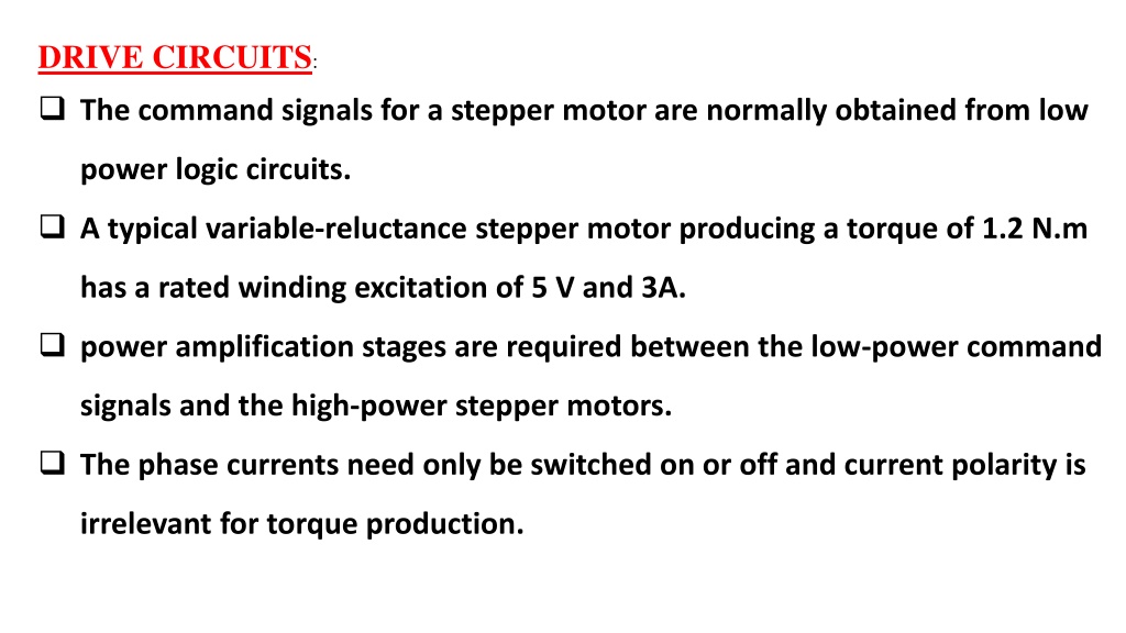
DRIVE CIRCUITS: The command signals for a stepper motor are normally obtained from low power logic circuits. A typical variable-reluctance stepper motor producing a torque of 1.2 N.m has a rated winding excitation of 5 V and 3A. power amplification stages are required between the low-power command signals and the high-power stepper motors. The phase currents need only be switched on or off and current polarity is irrelevant for torque production.
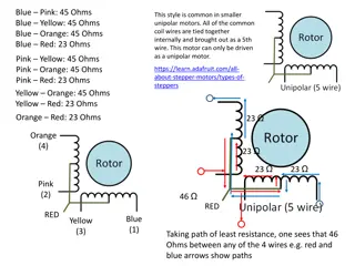
Permanent magnet stepper motors require two phases, and the current polarity is important. Unipolar Drive Circuit: The following figure shows a simple unipolar drive circuit suitable for a three-phase variable-reluctance stepper motor. Each phase winding is excited by a separate drive circuit. A phase winding is excited by applying a control signal to the base of the transistor. The control signal may require several stages of amplification before it attains the required current level for the base of the transistor.
Unipolar drive circuit for a three-phase variable-reluctance stepper motor.
The phase winding has a large inductance and so large time constant . The current buildup to its rated value in the phase winding is slow, causing unsatisfactory operation of the motor at high stepping rates. The addition of Rext decreases the electrical time constant, thereby speeding up the current buildup. When the base drive current is removed to switch off the transistor, a large induced voltage will appear across the transistor if the winding current is suddenly interrupted. The large voltage may permanently damage the transistor.
This possibility is avoided by providing an alternative path for the phase winding current known as a freewheeling path. Therefore, when the transistor is switched off, the phase winding current will continue to flow in the freewheeling diode Df and a freewheeling resistance Rf . The maximum voltage across the transistor occurs at the instant of switch off and the phase current will decay in the closed circuit formed by the phase winding, Df, Rf, and Rext. The magnetic energy stored in the phase inductance at turnoff of the transistor is dissipated in the resistances of this closed circuit
Example A 3-phase variable-reluctance stepper motor has the following parameters: Rw= 1 Lw= 30 mH, average phase winding inductance I = 3A, rated winding current Design a simple unipolar drive circuit such that the electrical time constant is 2 msec at phase turn-on and 1 msec at turnoff. The stepping rate is 300 steps per second.
Solution Solution The turn-on time constant This resistance must be able to dissipate the power lost when rated current flows through the phase winding continuously, namely
This energy is dissipated in Rf, Rext, and Rw . Since Rf = Rext + Rw Then the energy dissipated in Rf is 0.0675 J Since the stepping rate = 300 steps /sec. Number of turnoffs in each phase = 100 Average power dissipated in Rf = 100 x 0.0675 = 6.75 watt
When the transistor conducts, the reverse voltage across the diode Dfis Vs = 45 V. The peak current of the freewheeling diode is 3A, which is the phase winding current at the instant when the transistor turns off. VCE(max) = 45 + 3 x 15 = 90 V. Current rating of the transistor is 3A.
Bipolar Drive Circuit The following figure shows one phase of a bipolar drive circuit suitable for the permanent magnet stepper motor. The transistors are switched in pairs according to the current polarity required for the phase winding. Transistors Tl and T2 are turned on simultaneously so that current can flow from left to right in the phase winding.
If transistors T3 and T4 are turned on simultaneously, current will flow in the opposite direction. The four diodes Df are connected in antiparallel with the switching transistors to provide the paths for the freewheeling currents. when Tl and T2 are switched on, current flows from dc supply to T l, phase winding (left to right), T2, and back to dc supply.
When Tl and T2 are switched off , current in the phase winding cannot decay instantaneously because of winding inductance. The current therefore flows through diodes D3 and D4 to the dc supply, as shown in figure by dashed lines. Note that when current flows through and to the dc supply, some of the energy stored in the phase winding inductance at turnoff is returned to the supply. This improves the overall system efficiency.
Most large stepper motors (>I kW), including variable reluctance types, are operated from bipolar drive circuits. Bipolar drive circuits require more switching devices and are therefore more expensive than unipolar drive circuits. Note that the freewheeling currents in the bipolar drive circuit decay more rapidly than in the unipolar drive circuit, because the dc supply opposes them. Consequently no additional freewheeling resistance is necessary in the bipolar drive circuit
item Unipolar drive circuit Bipolar drive circuit Small because the energy stored in the phase winding inductance at turnoff is lost as a heat in the free wheeling circuit. High because some of the energy stored in the phase winding inductance at turnoff is returned to the supply. Efficiency it requires less switching devices more expensive because it requires more switching devices Cost Free wheeling resistance is not needed because the free wheeling currents decay more rapidly because the dc supply opposes them. necessary Application Small stepper motors large stepper motors (>1 kW)
Example : A stepper motor driven by a bipolar drive circuit has the following parameters: Winding inductance (average) = 30 mH Rated current = 3 A Total resistance in each phase R = 15 DC supply = 45 V When transistors are turned off, determine the: (a) Time taken by the phase current to decay to zero. (b) Proportion of the stored inductive energy returned to the dc supply.
Solution The equivalent circuit at turnoff is shown in figure. The current can be considered to have two components: One component of current is the initial current 3 A, which decays in Lw and R, with zero supply voltage, that is, ?? ?= 2 msec. ??= ?? ?/? where ? = The other component of current is ??, which is produced by the supply voltage Vs, assuming no initial current: ??= ?(? ? ? ?) Hence the net current is:
? = ??+ ??= ???/? ?(? ?? ?) = ? + ? ? ?/? Let fall to zero in time ??then: ? 0 = ? + ? ? ??/? ??= ?.? ????. Energy returned to the supply, Ws:


, including variable")