Volvo L45F Compact Wheel Loader Service Repair Manual Instant Download
Please open the website below to get the complete manualnn//
Download Presentation

Please find below an Image/Link to download the presentation.
The content on the website is provided AS IS for your information and personal use only. It may not be sold, licensed, or shared on other websites without obtaining consent from the author. Download presentation by click this link. If you encounter any issues during the download, it is possible that the publisher has removed the file from their server.
E N D
Presentation Transcript
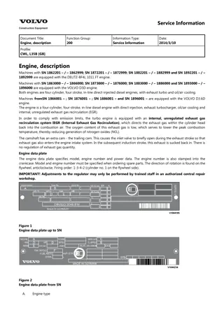
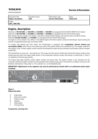
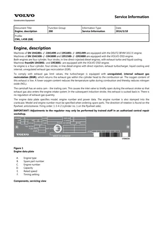
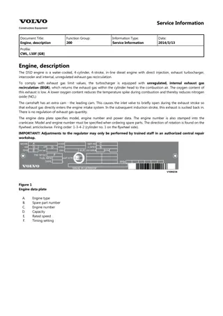
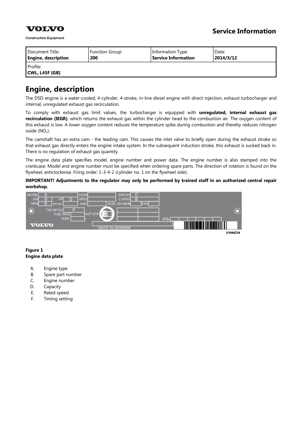
Service Information Document Title: Engine, description Function Group: 200 Information Type: Service Information Date: 2014/3/12 Profile: CWL, L45F [GB] Engine, description The D5D engine is a water-cooled, 4-cylinder, 4-stroke, in-line diesel engine with direct injection, exhaust turbocharger and internal, unregulated exhaust gas recirculation. To comply with exhaust gas limit values, the turbocharger is equipped with unregulated, internal exhaust gas recirculation (IEGR), which returns the exhaust gas within the cylinder head to the combustion air. The oxygen content of this exhaust is low. A lower oxygen content reduces the temperature spike during combustion and thereby reduces nitrogen oxide (NO?). The camshaft has an extra cam - the leading cam. This causes the inlet valve to briefly open during the exhaust stroke so that exhaust gas directly enters the engine intake system. In the subsequent induction stroke, this exhaust is sucked back in. There is no regulation of exhaust gas quantity. The engine data plate specifies model, engine number and power data. The engine number is also stamped into the crankcase. Model and engine number must be specified when ordering spare parts. The direction of rotation is found on the flywheel, anticlockwise. Firing order: 1-3-4-2 (cylinder no. 1 on the flywheel side). IMPORTANT! Adjustments to the regulator may only be performed by trained staff in an authorized central repair workshop. Figure 1 Engine data plate A. B. C. D. E. F. Engine type Spare part number Engine number Capacity Rated speed Timing setting
Service Information Document Title: Component locations Function Group: 200 Information Type: Service Information Date: 2014/3/12 Profile: CWL, L45F [GB] Component locations Components, servicing view Figure 1 Components, servicing view 1. 2. 3. 4. 5. 6. 7. 8. 9. Oil filler pipe Combustion air inlet Thermostat housing Coolant pump Alternator Crankshaft vibration damper Fuel pump Fuel filter Oil filter Oil cooler Attachment for power take-off Oil return line, crankcase ventilation Crankcase ventilation High-pressure pump Injector 10. 11. 12. 13. 14. 15. Components, exhaust view
Figure 2 Components, exhaust view 1. 2. 3. 4. 5. 6. 7. 8. 9. Crankcase ventilation Engine revolution governor Flywheel (SAE housing) Starter motor Turbocharger Alternator Thermostat housing Exhaust manifold Transport device
https://www.ebooklibonline.com Hello dear friend! Thank you very much for reading. Enter the link into your browser. The full manual is available for immediate download. https://www.ebooklibonline.com
Service Information Document Title: Compression test Function Group: 210 Information Type: Service Information Date: 2014/3/12 Profile: CWL, L45F [GB] Compression test Op nbr 210-002 9998694 Adapter 9988539 Pressure gauge 9998007 Adapter Injection valves are removed and valve clearance checked. Remove injection valves, see 237 Injectors all, testing and adjusting incl removing and fitting 1. Figure 1 Insert adapter (9998694) in injection valve bore with new seal ring. 2. Figure 2 Place clamping claw on adapter. Tighten screw.
3. Figure 3 If necessary, screw on adapter 9998007 for the connector. 4. Connect compression tester 9988539. Crank engine with the starter. 5. Carry out compression test on each cylinder. Compression: 3 +0.8 MPa (30 +8 bar) (435 +116 psi) NOTE! The compression measured depends on the starter rpm during the measurement and the engine's altitude. Therefore, exact limit valuescannot be set. Compression measurement is recommended only for comparison of all engine cylinders. If a deviation of more than 15% is found, the cylinder in question should be dismantled to determine the cause. 6. Install compression tester and connector. 7. Install injection valves.
Service Information Document Title: Engine, removing Function Group: 210 Information Type: Service Information Date: 2014/3/12 Profile: CWL, L45F [GB] Engine, removing Op nbr 210-070 1. Place the machine in service position. 2. Switch off the battery connection switch. WARNING The work involves handling heavy components - failure to stay alert may result in severe crushing injuries. 3. Remove the engine hood. Refer to 821 Engine hood, removing 4. Remove the counterweight. Refer to 716 Counterweight, removing 5. Drain coolant. Refer to 173 Coolant, changing 6. Drain the hydraulic oil, see 173 Hydraulic system, changing oil. 7. Undo the clamp and detach the charge air hose (1) from the charge air manifold (2) and radiator (3). Figure 1 NOTE! Plug all air hoses to the engine and radiator with suitable covers. 8. Detach the charge air hose (1) from the turbocharger.
Figure 2 9. Undo the clamp of the air filter intake hose (2) and remove it from the turbocharger and air filter. 10. Remove flexi exhaust pipe (1) from turbocharger. Figure 3 11. Detach all coolant hoses from the thermostat housing (1). Figure 4 NOTICE
When a hose has been disconnected, plug both the hose and the connection immediately. The hoses should be marked for correct connection. 12. Remove the V-belt cover, unscrewing the fixing bolts (1). Figure 5 13. Remove the clamp (1) at the compressor and unplug the electric pin plug connection (2). Figure 6 14. Detach the fuel hose (1) to the fuel feed pump and primary filter (fuel prefilter/water separator) at the bracket (2). Figure 7 15. Remove the air conditioning compressor. Undo the clamping strap bolt (1) and V-belt. Unscrew the compressor at the bracket (2) and move it downwards together with its hoses.
Figure 8 NOTICE Refrigerant under pressure. Do not disconnect any hoses or connections on the air conditioning, thereby involuntary releasing refrigerant. 16. Unplug the electric pin plug connection of the coolant expansion tank (1) and the windscreen washer fluid reservoir (2). Figure 9 17. Unplug the electric pin plug connection X22 (1), X23 (2) and unclamp the ground connection (3). Figure 10 18. Unplug the electric pin plug connection from the coolant temperature sensor (1) and crankshaft rpm sensor (2).
Figure 11 19. Unplug the electric pin plug connection of the hydrostatic pump (1) and emergency steering pump (2). Figure 12 20. Remove the cable tie and the cable harness fixing clamps. 21. Detach the ground cable (1) at the connection flange of the hydrostatic pump.
Figure 13 22. Detach the cab heat feed pipe (1) from the oil cooler housing. Figure 14 23. Detach the fuel return line (2) at the cover plate. 24. Remove the throttle cable bracket (1) at the governor housing and undo the lock nut (2). Figure 15 25. Detach the hydraulic lines from the steering pump.
Figure 16 Steering pump NOTICE When a hose has been disconnected, plug both the hose and the connection immediately. The hoses should be marked for correct connection. 26. Remove the clamp with hose assembly at the flywheel housing. Figure 17 27. Detach the hydraulic lines from the hydrostatic pump. Figure 18 Hydrostatic pump
28. Detach the hydraulic lines from the working hydraulics pump. Figure 19 Working hydraulics pump 29. Attach a crane hoist to the engine lifting eyes. Figure 20 30. Remove the engine bracket fixing bolts (frame/rubber elements). 31. Slowly out the engine and place it on a suitable surface. NOTE! Engine weight with steering pump, working hydraulics pump and hydrostatic pump removed - approx. 550 kg (1212 lb).
Service Information Document Title: Engine, installing Function Group: 210 Information Type: Service Information Date: 2014/3/12 Profile: CWL, L45F [GB] Engine, installing Op nbr 210-072 WARNING The work involves handling heavy components - failure to stay alert may result in severe crushing injuries. 1. Transfer the steering pump to the new engine. 2. Transfer the hydrostatic pump with connection flange to the new engine. Refer to 442 Hydraulic pump, replacing 3. Attach a crane hoist to the engine lifting eyes. Slowly lower the engine into the engine compartment and position it on the engine bearings. NOTICE Make sure that no hoses or cables are trapped. NOTE! Engine weight with steering pump, working hydraulics pump and hydrostatic pump removed - approx. 550 kg (1212 lb). Figure 1 4. Fit the engine bracket fixing bolts (frame/rubber elements). Tightening torque 85 + 5 Nm (63 + 4 lbf ft). 5. Attach the hydraulic lines to the working hydraulics pump.
Suggest: If the above button click is invalid. Please download this document first, and then click the above link to download the complete manual. Thank you so much for reading
Figure 2 Working hydraulics pump 6. Attach the hydraulic lines to the working hydrostatic pump. Figure 3 Hydrostatic pump 7. Fit the clamp (1) with hose assembly at the flywheel housing. Figure 4 8. Attach the hydraulic lines to the steering pump.
https://www.ebooklibonline.com Hello dear friend! Thank you very much for reading. Enter the link into your browser. The full manual is available for immediate download. https://www.ebooklibonline.com

