VOLVO DD112HF ASPHALT COMPACTOR Service Repair Manual Instant Download
Please open the website below to get the complete manualnn//
Download Presentation

Please find below an Image/Link to download the presentation.
The content on the website is provided AS IS for your information and personal use only. It may not be sold, licensed, or shared on other websites without obtaining consent from the author. Download presentation by click this link. If you encounter any issues during the download, it is possible that the publisher has removed the file from their server.
E N D
Presentation Transcript
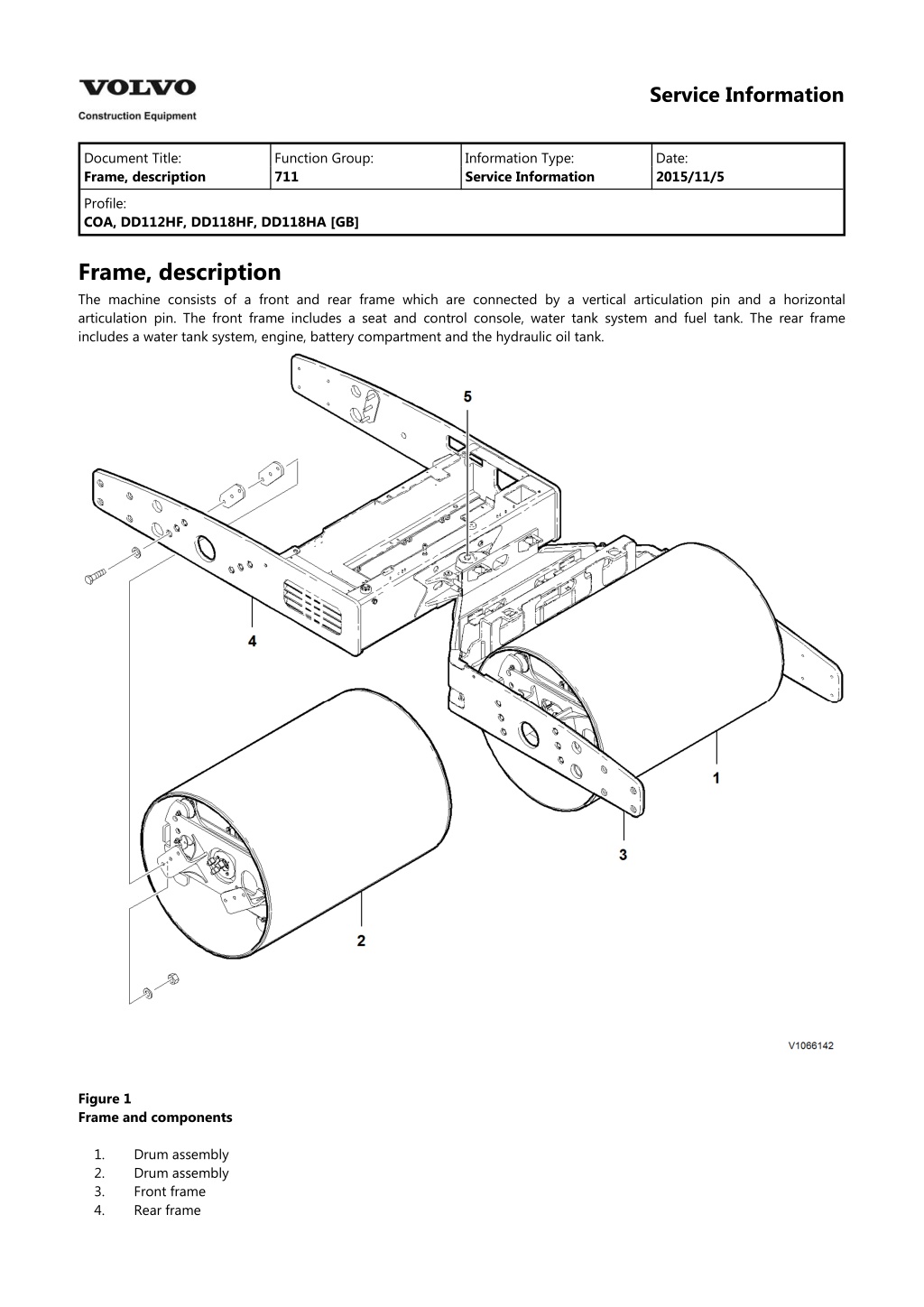
Service Information Document Title: Frame, description Function Group: 711 Information Type: Service Information Date: 2015/11/5 Profile: COA, DD112HF, DD118HF, DD118HA [GB] Frame, description The machine consists of a front and rear frame which are connected by a vertical articulation pin and a horizontal articulation pin. The front frame includes a seat and control console, water tank system and fuel tank. The rear frame includes a water tank system, engine, battery compartment and the hydraulic oil tank. Figure 1 Frame and components 1. 2. 3. 4. Drum assembly Drum assembly Front frame Rear frame
5. Articulation pin
Service Information Document Title: Drum, description Function Group: 777 Information Type: Service Information Date: 2015/11/5 Profile: COA, DD112HF, DD118HF, DD118HA [GB] Drum, description To meet varying job requirements, the operator can manually select individual drum amplitude plus dual drum, front drum or rear drum vibration. The DD112HF is equipped with a high/low amplitude selector switch. The DD118 compactor series of models has 8 amplitude settings which are manually set via an adjusting wheel on each drum. Vibration is achieved with an eccentric weight that rotates inside each drum. There is a direct 1:1 relationship between the eccentric shaft speed and the speed of vibration: one eccentric shaft rotation equals one impact. Eccentric(s) direction of rotation can be controlled automatically or manually. Eccentric speed is automatically controlled dependent upon amplitude setting. Drum vibration is started by pressing the vibration ON/OFF switch on the hydrostatic control forward-stop-reverse lever. Vibration starts immediately when in the manual mode. When the auto vibration mode is selected, vibration is enabled with the push button on the forward-stop-reverse control lever, but will not start until the compactor reaches a pre-set speed. In order for the vibration system to operate, the engine must be at high idle, as selected by the engine idle speed switch and the travel speed must be set for compaction by the travel speed switch.
https://www.ebooklibonline.com Hello dear friend! Thank you very much for reading. Enter the link into your browser. The full manual is available for immediate download. https://www.ebooklibonline.com
Figure 1 Drums and components 1. 2. 3. 4. 5. 6. 7. 8. Drum assembly Drum assembly Shim Shim Hexagon screw Nut Washer Washer
Service Information Document Title: Drum eccentric, description 777 Function Group: Information Type: Service Information Date: 2015/11/5 Profile: COA, DD112HF, DD118HF, DD118HA [GB] Drum eccentric, description The drums are each equipped with an eccentric, mounted internally which acts in a centrafugal manner. The purpose of the eccentric is to provide vibration to the drum, which aids in the compaction of the asphalt. The eccentric can be activated by a switch in the operator's platform and has 8 amplitude settings (2 amplitude settings on the DD112HF). These amplitude settings are manually set via an adjusting wheel on each drum.
Figure 1 Drum eccentric and components 1. 2. Eccentric tube Eccentric shaft
3. 4. 5. 6. 7. 8. 9. Eccentric journal Eccentric journal Roll pin Coupling Bearing Hexagon screw Hand wheel shaft O-ring Shaft end Spring Coupling Key Wear sleeve Washer Washer Hexagon screw Oil slinger Retaining ring 10. 11. 12. 13. 14. 15. 16. 17. 18. 19. 20.
Service Information Document Title: Eccentric shaft coupling, replacing Function Group: 777 Information Type: Service Information Date: 2015/11/5 Profile: COA, DD112HF, DD118HFA, DD118HF, DD118HA [GB] Eccentric shaft coupling, replacing Op nbr 777-010 Suitable container Removing 191 Service position 1. Place the machine in the Service Position. Refer to . 2.NOTICE Always handle oils and other environmentally hazardous fluids in an environmentally safe manner. Place a suitable container underneath the vibration motor to catch any oil that may leak from the motor upon removal. 3. Remove the two hexagon screws at the vibration motor on the left side of the drum. Remove the vibration motor away from the machine. 4. Remove the coupling and shaft from the eccentric weight. Figure 1 Eccentric coupling and shaft 1. 2. 3. Shaft Coupling Vibration motor Installing 5. Lubricate the new shaft and coupling. Insert the shaft into the eccentric weight. 6. Lightly coat the coupling with an approved lubricant. Install the coupling onto the splined shaft of the vibration motor. 7. Before re-installing the vibration motor, inspect the O-ring on the mounting flange and replace, if necessary.
8. Lift the vibration motor into position at the machine. 9. Re-install the hexagon screws at the vibration motor. Use a thread locking compound and torque the hexagon screws to specification. Refer to 030 Tightening torque, specifications . 10. Repeat the above steps for the other drum. 11. Place the machine back in service.
Service Information Document Title: Drum, removing Function Group: 777 Information Type: Service Information Date: 2015/11/5 Profile: COA, DD112HF, DD118HFA, DD118HF, DD118HA [GB] Drum, removing Op nbr 777-001 Lifting device Lifting strap, 2m Support stands Wooden blocks Container 191 Service position 1. Place the machine in the Service Position. Refer to . 2. Lift the frame using a suitable lifting device to take the weight off the shock mounts. Figure 1 Lifting device and support stand underneath the drum frame 3. Place suitable support stands underneath the back of the frame. 4. Repeat steps 2 and 3 for the other side of the drum. 5. NOTE! Be sure that the water tank has been drained before removal. Remove the wiring harness cover at the inside of the frame. Disconnect the wiring harnesses for the water pumps and lights. 6. Remove the hexagon screws that retain the water tank and front beam to the drum frame. NOTE! Identify and retain the shims for re-installation. WARNING Only use lifting devices with adequate capacity. 7. Attach a suitable lifting device at the water tank and front beam assembly. Carefully and safely, lift the water tank and front beam assembly out and away from the machine. Weight of water tank and front beam assembly 425 kg (937 lbs)
NOTE! Do not let the water tank and front beam assembly rest on the scraper bar when placing the assembly on the floor. Figure 2 Water tank and front beam assembly on blocks of wood 8. Remove the hexagon screws at the drum lights. Lay the drum lights off to one side and out of the way. Figure 3 Drum lights on the inside of the drum 9. Place a suitable container underneath the vibration motor to catch any oil that may escape. Remove the hexagon screws that retain the vibration motor to the drum. Lay the vibration motor and hydraulic hoses off to the side. 10. At the drum drive side of the machine, disconnect the clamps and the wiring harness at the hand wheel for the amplitude speed sensor. Pull the wiring harness through the speed sensor support shaft. Lay the wiring harness off to one side and out of the way.
Figure 4 Clamps and amplitude speed sensor 1. 2. Clamp Amplitude speed sensor 11. Remove the amplitude speed sensor bracket at the hand wheel. 12. Remove the hexagon screws at the speed sensor support shaft and remove the shaft from the machine. Figure 5 Hexagon screws at the speed sensor support shaft 13. Disconnect the wiring harness for the drum drive motor. 14. NOTE! Identify the hydraulic hoses before disconnecting them. Place a suitable container underneath the drum drive motor to catch any oil that may escape. Disconnect the hydraulic hoses at the drum drive motor. Plug and cap the hoses immediately to prevent contamination of the hydraulic system. 15. Remove the hexagon screws that retain the drum to the frame. Figure 6 Hexagon screws that retain the drum to the frame NOTE! Identify and retain the shims for re-installation. 16. Carefully and safely, roll the drum out and away from the drum frame. NOTE! Use suitable wedges or chocks to secure the drum in a fixed position. 17. Repeat the above steps for the other drum.
Suggest: For more complete manuals. Please go to the home page. https://www.ebooklibonline.com If the above button click is invalid. Please download this document first, and then click the above link to download the complete manual. Thank you so much for reading
Service Information Document Title: Drum, installing Function Group: 777 Information Type: Service Information Date: 2015/11/5 Profile: COA, DD112HF, DD118HFA, DD118HF, DD118HA [GB] Drum, installing Op nbr 777-002 Hand pump Container 1. Remove the shock mounts from the old drum and install them at the new drum. 173 Drum eccentric, changing oil 173 Drum carrier, changing oil 2. Fill the drum with clean oil. Refer to and . 3. Carefully and safely, roll the drum into position at the drum frame. 4. Install a suitable hand pump at the drum drive motor to manually release the brake in order to line up the holes on the torque hub with the frame. NOTE! Do not exceed 24 bar (350 psi). Excessive pressure may result in seal damage. 5. Re-install the hexagon screws and shims that retain the drum to the frame. Do not tighten the hexagon screws at this point. Figure 1 Hexagon screws that retain the drum to the frame WARNING Only use lifting devices with adequate capacity. 6. Carefully and safely, lift the water tank and front beam assembly into place at the drum. Weight of water tank and front beam assembly 425 kg (937 lbs) 7. Re-install the shims and hexagon screws that retain the water tank and front beam assembly to the drum frame. Do not tighten the hexagon screws at this point. 8. Using a suitable locking compound, torque tighten the hexagon screws that retain the drum to the frame. Refer to . 030 Critical mounting torques 9. Using a suitable locking compound, torque tighten the hexagon screws that retain the water tank and front beam
030 Tightening torque, specifications assembly to the frame. Refer to . 10. Re-install the hydraulic hoses at the drum drive motor. 11. Connect the wiring harness for the drum drive motor. 12. Re-install the speed sensor support shaft. Retain the shaft with the hexagon screws. Figure 2 Hexagon screws at the speed sensor support shaft 13. NOTE! Feed the speed sensor wiring harness through the speed sensor support shaft before re-installing the amplitude speed sensor bracket. Re-install the amplitude speed sensor bracket at the hand wheel. 14. Re-install the clamps and the wiring harness at the hand wheel for the amplitude speed sensor. NOTE! Be sure that the speed sensor and the magnet on the indicator are positioned so that they meet when the drum turns. Figure 3 Clamps and amplitude speed sensor 1. 2. Clamp Amplitude speed sensor 15. Re-install the vibration motor to the drum. Using a suitable thread locking compound, torque the hexagon screws
https://www.ebooklibonline.com Hello dear friend! Thank you very much for reading. Enter the link into your browser. The full manual is available for immediate download. https://www.ebooklibonline.com

