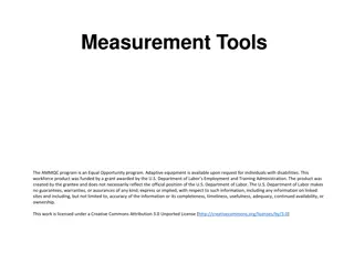
Vernier Caliper: Precise Measurement Instrument
Measuring Instruments
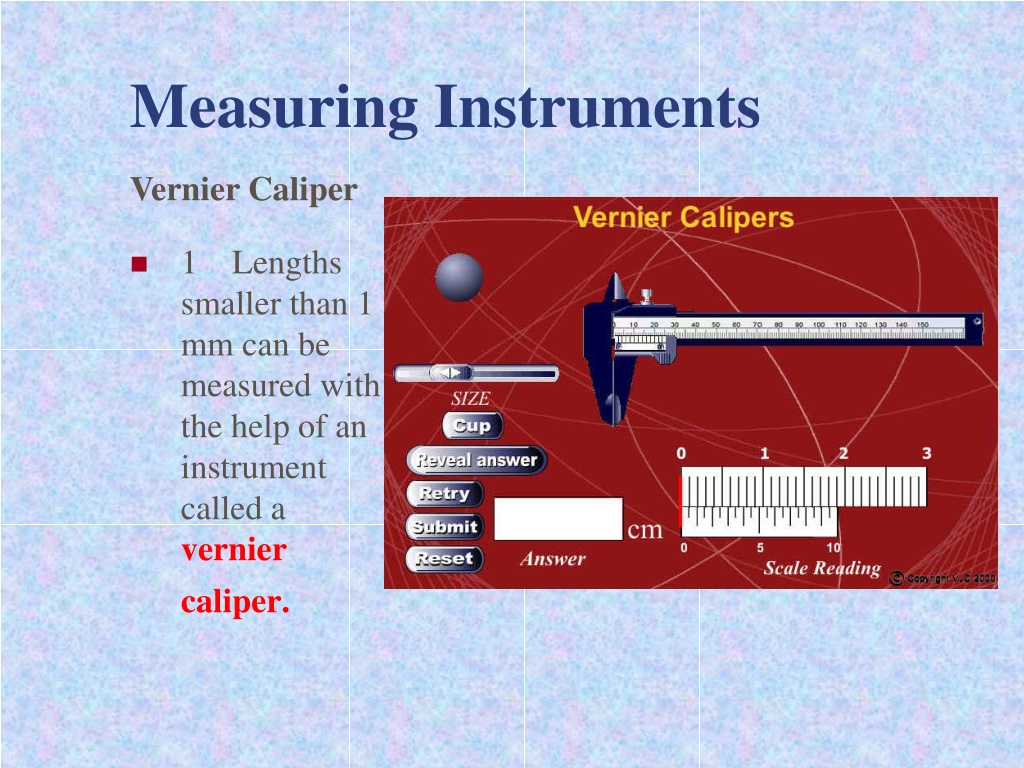
1
Lengths
smaller than 1
mm can be
measured with
the help of an
instrument
called a
vernier
caliper.
Vernier Caliper
Measuring Instruments
Vernier Caliper
2
A vernier caliper is used to measure an object
with dimensions up to 12 cm with an accuracy of
0.01 cm
.
Measuring Instruments
Vernier Caliper
3
There are two pairs of
jaws, one is designed to
measure linear dimensions
and
external diameters
while the other is to measure
internal diameters
.
Measuring Instruments
Vernier Caliper
4.
To measure with a vernier caliper, slide the vernier
scale along the main scale until the object is held firmly
between the jaws of the caliper. The subsequent steps are
as follows.
Measuring Instruments
Vernier Caliper
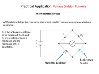
(a)The reading on the main scale is determined with
reference to the `0' mark on the vernier scale. The reading
to be taken on the main scale is the mark preceding the
Figure 1.10 shows that the '0' mark on the vernier scale
lies between 3.2 cm and 3.3 cm. The reading to be taken
on the main scale is 3.2 cm (the `0' mark on the vernier
scale acts as a pointer).
1
Measuring Instruments
Vernier Caliper
(b) The reading to be taken on the vernier scale is indicated by the
mark on the vernier scale which is exactly in line or
coincides
with
any main scale division line. Figure 1.10 shows that the
fourth mark
on the vernier scale is exactly in line with a mark on the main scale.
Thus the second decimal reading of the measurement is:
Vernier scale reading = 4 x 0.01 cm
= 0.04 cm
2
Measuring Instruments
Vernier Caliper
(c)
The reading of the vernier caliper is the result of the
addition
of the reading on the main scale to the reading on
the vernier scale.
3.2
0.04
Measuring Instruments
Vernier Caliper
(c)
The reading of the vernier caliper is the result of the
addition of the reading on the main scale to the reading on
the vernier scale.
Caliper reading = Main scale Reading + Vernier scale
reading
Thus the reading of the vernier caliper in Figure 1.10 is
=
3.2 + 0.04 = 3.24 cm
3.2
0.04
Measuring Instruments
Vernier Caliper
5.
A vernier caliper has a zero error if the `0'
mark on the main scale is not in line with the '0'
mark on the vernier scale when the jaws of the
caliper are fully closed
Measuring Instruments
Vernier Caliper
(a) Positive zero error
Zero error =
+0.04 cm
.
Measuring Instruments
0.72 cm
0.70 cm
0.02cm
Measuring Instruments
Vernier Caliper
(b)
Negative zero error
Zero error =
-0.02 cm
.
The result of measuring is :
( 3 mm + ( 7 x 0.1 ) mm ) = 3.7 mm
Measuring Instruments
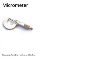
Micrometer Screw Gauge
1
A micrometer screw gauge is used to measure
small lengths ranging between 0.10 mm and
25.00 mm
.
Measuring Instruments
Micrometer Screw Gauge
2
This instrument can be used to measure diameters
of wires and thicknesses of steel plates to an
accuracy of
0.01 mm
.
Measuring Instruments
Micrometer Screw Gauge
3
The micrometer scale comprises a
main scale
marked on
the sleeve and a scale marked on the thimble called the
thimble scale
.
Measuring Instruments
Micrometer Screw Gauge
4
The difference between one division on the upper scale
and one division on the lower scale is 0.5 mm.
Measuring Instruments
Micrometer Screw Gauge
5
The thimble scale is subdivided into 50 equal divisions.
When the thimble is rotated through one complete turn, i.e.
360
, the gap between the anvil and the spindle increases
by 0.50 mm.
Measuring Instruments
Micrometer Screw Gauge
6
This means that one division on the thimble scale
is = 0.01 mm.
Measuring Instruments
Micrometer Screw Gauge
7
When taking a reading, the thimble is turned until
the object is gripped very gently between the
anvil and the spindle.
Measuring Instruments
Micrometer Screw Gauge
8
The ratchet knob is then turned until a `click'
sound is heard.
Measuring Instruments
Micrometer Screw Gauge
9
The ratchet knob is used to
prevent the user
from exerting undue pressure
.
Measuring Instruments
Micrometer Screw Gauge
10
The grip on the object must not be excessive as
this will affect the accuracy of the reading.
Measuring Instruments
Micrometer Screw Gauge
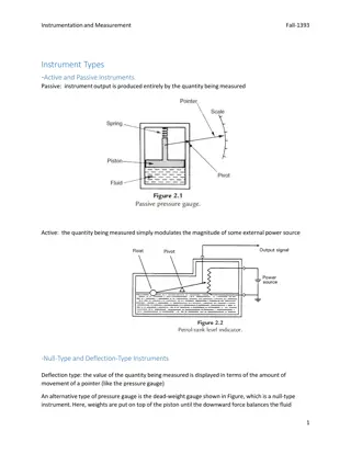
11
Readings on the micrometer are taken as follows.
(a) The last graduation showing on the main scale
indicates position
between 2.0 mm and 2.5 mm
.
Thus the reading on the main scale is read as 2.0
mm.
Measuring Instruments
Micrometer Screw Gauge
11
Readings on the micrometer are taken as follows.
(b) The reading of the micrometer screw gauge is the
sun of the main scale reading and the thimble
scale reading which is:
2.0 + 0.22 =2.22 mm
Measuring Instruments
Micrometer Screw Gauge
11
Readings on the micrometer are taken as follows.
(b) The reading on the thimble scale is the point
where the horizontal reference line of the main
scale is in line with the graduation mark on the
thimble scale Figure 1.15(b) shows this to be the
22nd mark
on the thimble scale, thus giving a
reading of 22 x 0.01 mm = 0.22 mm.
Measuring Instruments
Micrometer Screw Gauge
12
Readings on the micrometer are taken as follows.
(a) Positive zero error
In Figure 1.16, the horizontal reference line in the main
scale is in line with the
4
th
division mark
, on the positive
side of the `0' mark, on the thimble scale. The error of
+0.04 mm must be subtracted from all readings taken.
Zero error =
+0.04 mm
Measuring Instruments
Micrometer Screw Gauge
13
(b)
Negative zero error
In Figure 1.17, the horizontal reference line on
the main scale is in line with the 3
rd
division mark,
below the `0' mark of the thimble scale.
Zero error =
-0.03 mm
Vernier caliper is a precise measuring instrument used for measurements smaller than 1 mm with an accuracy up to 0.01 cm. It consists of two pairs of jaws for measuring linear dimensions, external, and internal diameters. The steps to measure with a vernier caliper involve aligning the main scale and vernier scale, determining readings on both scales, and adding them for the final measurement result.

Download Presentation

Please find below an Image/Link to download the presentation.
The content on the website is provided AS IS for your information and personal use only. It may not be sold, licensed, or shared on other websites without obtaining consent from the author.If you encounter any issues during the download, it is possible that the publisher has removed the file from their server.
You are allowed to download the files provided on this website for personal or commercial use, subject to the condition that they are used lawfully. All files are the property of their respective owners.
The content on the website is provided AS IS for your information and personal use only. It may not be sold, licensed, or shared on other websites without obtaining consent from the author.
E N D
Presentation Transcript
Measuring Instruments Vernier Caliper 1 Lengths smaller than 1 mm can be measured with the help of an instrument called a vernier caliper.
Measuring Instruments Vernier Caliper 2 A vernier caliper is used to measure an object with dimensions up to 12 cm with an accuracy of 0.01 cm.
Measuring Instruments Vernier Caliper 3 There are two pairs of jaws, one is designed to measure linear dimensions and external diameters while the other is to measure internal diameters.
Measuring Instruments Vernier Caliper 4. To measure with a vernier caliper, slide the vernier scale along the main scale until the object is held firmly between the jaws of the caliper. The subsequent steps are as follows.
Measuring Instruments Vernier Caliper (a)The reading on the main scale is determined with reference to the `0' mark on the vernier scale. The reading to be taken on the main scale is the mark preceding the Figure 1.10 shows that the '0' mark on the vernier scale lies between 3.2 cm and 3.3 cm. The reading to be taken on the main scale is 3.2 cm (the `0' mark on the vernier scale acts as a pointer). 1
Measuring Instruments Vernier Caliper (b) The reading to be taken on the vernier scale is indicated by the mark on the vernier scale which is exactly in line or coincides with any main scale division line. Figure 1.10 shows that the fourth mark on the vernier scale is exactly in line with a mark on the main scale. Thus the second decimal reading of the measurement is: Vernier scale reading = 4 x 0.01 cm = 0.04 cm 2
Measuring Instruments 0.04 Vernier Caliper 3.2 (c) The reading of the vernier caliper is the result of the addition of the reading on the main scale to the reading on the vernier scale.
Measuring Instruments 0.04 Vernier Caliper 3.2 (c) The reading of the vernier caliper is the result of the addition of the reading on the main scale to the reading on the vernier scale. Caliper reading = Main scale Reading + Vernier scale reading Thus the reading of the vernier caliper in Figure 1.10 is = 3.2 + 0.04 = 3.24 cm
Measuring Instruments Vernier Caliper 5. A vernier caliper has a zero error if the `0' mark on the main scale is not in line with the '0' mark on the vernier scale when the jaws of the caliper are fully closed
Measuring Instruments Vernier Caliper (a) Positive zero error Zero error = +0.04 cm.
Measuring Instruments 0.02cm 0.70 cm 0.72 cm
Measuring Instruments Vernier Caliper (b) Negative zero error Zero error = -0.02 cm.
6 mm ( 2 x 0.1 ) mm The result of measuring is ( 6 mm + 0.2 mm ) = 6.2 mm
The result of measuring is : ( 3 mm + ( 7 x 0.1 ) mm ) = 3.7 mm
Measuring Instruments Micrometer Screw Gauge 1 A micrometer screw gauge is used to measure small lengths ranging between 0.10 mm and 25.00 mm.
Measuring Instruments Micrometer Screw Gauge 2 This instrument can be used to measure diameters of wires and thicknesses of steel plates to an accuracy of 0.01 mm.
Measuring Instruments Micrometer Screw Gauge 3 The micrometer scale comprises a main scale marked on the sleeve and a scale marked on the thimble called the thimble scale.
Measuring Instruments Micrometer Screw Gauge 4 The difference between one division on the upper scale and one division on the lower scale is 0.5 mm.
Measuring Instruments Micrometer Screw Gauge 5 The thimble scale is subdivided into 50 equal divisions. When the thimble is rotated through one complete turn, i.e. 360 , the gap between the anvil and the spindle increases by 0.50 mm.
Measuring Instruments Micrometer Screw Gauge 6 This means that one division on the thimble scale is = 0.01 mm. 5 . 0 mm 50
Measuring Instruments Micrometer Screw Gauge 7 When taking a reading, the thimble is turned until the object is gripped very gently between the anvil and the spindle.
Measuring Instruments Micrometer Screw Gauge 8 The ratchet knob is then turned until a `click' sound is heard.
Measuring Instruments Micrometer Screw Gauge 9 The ratchet knob is used to prevent the user from exerting undue pressure.
Measuring Instruments Micrometer Screw Gauge 10 The grip on the object must not be excessive as this will affect the accuracy of the reading.
Measuring Instruments Micrometer Screw Gauge 11 Readings on the micrometer are taken as follows. (a) The last graduation showing on the main scale indicates position between 2.0 mm and 2.5 mm. Thus the reading on the main scale is read as 2.0 mm.
Measuring Instruments Micrometer Screw Gauge 11 Readings on the micrometer are taken as follows. (b) The reading of the micrometer screw gauge is the sun of the main scale reading and the thimble scale reading which is: 2.0 + 0.22 =2.22 mm
Measuring Instruments Micrometer Screw Gauge 11 Readings on the micrometer are taken as follows. (b) The reading on the thimble scale is the point where the horizontal reference line of the main scale is in line with the graduation mark on the thimble scale Figure 1.15(b) shows this to be the 22nd mark on the thimble scale, thus giving a reading of 22 x 0.01 mm = 0.22 mm.
Measuring Instruments Micrometer Screw Gauge 12 Readings on the micrometer are taken as follows. (a) Positive zero error In Figure 1.16, the horizontal reference line in the main scale is in line with the 4th division mark, on the positive side of the `0' mark, on the thimble scale. The error of +0.04 mm must be subtracted from all readings taken. Zero error = +0.04 mm
Measuring Instruments Micrometer Screw Gauge 13(b) Negative zero error In Figure 1.17, the horizontal reference line on the main scale is in line with the 3rd division mark, below the `0' mark of the thimble scale. Zero error = -0.03 mm


 mm")