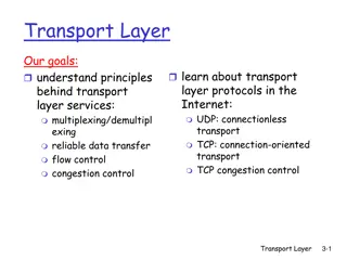
Understanding the Network Layer in Computer Networking

The network layer is vital in computer networking, responsible for host-to-host delivery by carrying packets between computers. It enables internetworking, routing packets to their destinations, and ensuring unique addressing for global communication. This layer encapsulates data packets, fragments them as needed, and uses IP addresses to uniquely identify devices for seamless connectivity in the Internet model.

Download Presentation

Please find below an Image/Link to download the presentation.
The content on the website is provided AS IS for your information and personal use only. It may not be sold, licensed, or shared on other websites without obtaining consent from the author. Download presentation by click this link. If you encounter any issues during the download, it is possible that the publisher has removed the file from their server.
E N D
Presentation Transcript
Network Layer Dr. Hussam Akif Al-Ameen
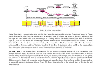
The network layer in the Internet model (and OSI model) is responsible for carrying a packet from one computer to another, it is responsible for host-to- host delivery. The two network-layer protocols in the source and destinations computers cooperate to supervise the delivery of a message. The main service the network layer receives from the data link layer is the delivery of data node-to-node. If there are N nodes between the source and destination hosts, there are N node-to-node deliveries to achieve a host-to- host delivery at the network layer.
Internetworking The main duty of the network layer is to provide internetworking, the logical gathering of different physical network together to look like a single network to the upper layers. Addressing communication at the network layer is host-to-host (computer-to-computer); a computer somewhere in the world needs to communicate with another computer somewhere else in the world. Usually, computers communicate through the Internet. The packet transmitted by the sending computer may pass through several LANs or WANs before reaching the destination computer. For this level of communication, we need a global addressing scheme; we called this logical addressing or IP address to mean a logical address in the network layer of the TCP/IP protocol suite. Routing The Network layer must provide services to direct packets to their destination host. The source and destination hosts are not always connected to the same network. In fact, the packet might have to travel through many different networks. Intermediary devices that connect the networks are called routers. The role of the router is to select paths for and direct packets toward their destination. This process is known as routing.
Packetizing (Encapsulation) Not only must the devices be identified with an address, the individual pieces - the Network layer PDUs - must also contain these addresses. During the packetizing process, Layer 3 receives the Layer 4 PDU and adds a Layer 3 header to create the Layer 3 PDU. When referring to the Network layer, we call this PDU a packet. When a packet is created, the header must contain, among other information, the address of the host to which it is being sent (destination address). The Layer 3 header also contains the address of the originating host (source address). Fragmenting Some physical networks are not able to encapsulate a packet of specific size in their frames. The packet must be fragmented to be able to pass through those networks.
Addressing and Routing At the network layer, we need to uniquely identify each device on the Internet to allow global communication between all devices. This is analogous to the telephone system, where each telephone subscriber has a unique telephone number, given that the country code and the area code are part of the identifying scheme. The identifier used in the network layer of the Internet model to identify each device connected to the Internet is called the Internet address or IP address. IP address An IP address, in the current version of the protocol IPv4 (IP version 4), is a 32- bit binary address that uniquely and universally defines the connection of a host or a router to the Internet. IP addresses are unique. They are unique in the sense that each address defines one, and only one, connection to the Internet. Two devices on the Internet can never have the same address at the same time.
If a device operating at the network layer has m connections to the Internet, it needs to have m addresses. We will see later that a router is such a device. The IP addresses are universal in the sense that the addressing system must be accepted by any host that wants to be connected to the Internet. Address Space A protocol such as IPv4 that defines addresses has an address space. An address space is the total number of addresses used by the protocol. If a protocol uses N bits to define an address, the address space is 2N IPv4 uses 32-bit addresses, which means that the address space is 232 or 4,294,967,296 (more than 4 billion). This means that, theoretically, if there were no restrictions, more than 4 billion devices could be connected to the Internet. The actual number is much less because of the restrictions imposed on the addresses.
Notations There are two prevalent notations to show an IP address: binary notation and dotted decimal notation. Binary Notation In binary notation, the IP address is displayed as 32 bits. Each octet is often referred to as a byte. So it is common to hear an IP address referred to as a 32-bit address or a 4-byte address. example of an IP address in binary notation: 01110101 10010101 00011101 00000010 Dotted-Decimal Notation To make the IP address more compact and easier to read, Internet addresses are usually written in decimal form with a decimal point (dot) separating the bytes. The following is the dotted-decimal notation of the above address: 117.149.29.2
Example : An IP address in both binary and dotted-decimal notation. Because each byte (octet) is 8 bits, each number in dotted-decimal notation is a value ranging from 0 to 255. Example : Change the following IP addresses from binary notation to dotted-decimal notation. a. 10000001 00001011 00001011 11101111 b. 11111001 10011011 11111011 00001111
We replace each group of 8 bits with its equivalent decimal number and add dots for separation: a. 129.11.11.239 b. 249.155.251.15 Example : Change the following IP addresses from dotted-decimal notation to binary notation. a. 111.56.45.78 b. 75.45.34.78 We replace each decimal number with its binary equivalent (see Appendix B): a. b. 01101111 00111000 00101101 01001110 01001011 00101101 00100010 01001110
Classful Addressing IPv4 addressing, at its inception, used the concept of classes. This architecture is called classful addressing. In the mid-1990s, a new architecture, called classless addressing, was introduced. In classful addressing, the IP address space is divided into five classes: A, B, C, D, and E. Each class occupies some part of the address space. We can find the class of an address when given the address in binary notation or dotted-decimal notation. If the address is given in binary notation, the first few bits can immediately tell us the class of the address. If the address is given in decimal-dotted notation, the first byte defines the class.
Example : Find the class of each address: a.00000001 00001011 00001011 11101111 b. 11110011 10011011 11111011 00001111 c. 227.12.14.87 d. 252.5.15.111 e. 134.11.78.56 a. The first bit is 0; this is a class A address. b. The first 4 bits are 1s; this is a class E address. c. The first byte is 227 (between 224 and 239); the class is D. d. The first byte is 252 (between 240 and 255); the class is E. e. The first byte is 134 (between 128 and 191); the class is B.
Addresses in classes A, B, and C are for unicast communication, from one source to one destination. A host needs to have at least one unicast address to be able to send or receive packets. Addresses in class D are for multicast communication, from one source to a group of destinations. If a host belongs to a group or groups, it may have one or more multicast addresses. A multicast address can be used only as a destination address, but never as a source address. Addresses in class E are reserved. The original idea was to use them for special purposes. They have been used only in a few cases.

")

")