Understanding Soil Compaction in Engineering Projects
Learn about soil compaction, a vital process in engineering projects, which involves densifying soils through mechanical energy application to improve various properties such as strength, permeability, and compressibility. Find out about factors influencing compaction, advantages, different types, and standard testing methods like the Proctor test. Explore how water content, compaction effort, and soil type affect the compaction process. Discover the significance of maximum dry density and optimum water content in achieving optimal soil compaction. Gain insights into the impact of compaction on reducing void ratio, increasing degree of saturation, and enhancing shear strength.

Download Presentation

Please find below an Image/Link to download the presentation.
The content on the website is provided AS IS for your information and personal use only. It may not be sold, licensed, or shared on other websites without obtaining consent from the author. If you encounter any issues during the download, it is possible that the publisher has removed the file from their server.
You are allowed to download the files provided on this website for personal or commercial use, subject to the condition that they are used lawfully. All files are the property of their respective owners.
The content on the website is provided AS IS for your information and personal use only. It may not be sold, licensed, or shared on other websites without obtaining consent from the author.
E N D
Presentation Transcript
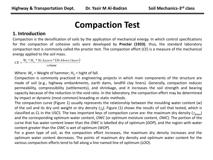
Highway & Transportation Dept. Dr. Yasir M Al-Badran Soil Mechanics-3rd class Compaction Test 1. Introduction Compaction is the densification of soils by the application of mechanical energy. In which control specifications for the compaction of cohesive soils were developed by Procter (1933); thus, the standard laboratory compaction test is commonly called the proctor test. The compaction effort (CE) is a measure of the mechanical energy applied to the soil mass. ( ) volume * * . * blows . / W H Nr Layers Nr layer = h h CE Where: Wh = Weight of hammer; Hh = hight of fall. Compaction is commonly practiced in engineering projects in which main components of the structure are made of soil (e.g., highway embankments, earth dams, landfill clay liners). Generally, compaction reduces permeability, compressibility (settlements), and shrinkage, and it increases the soil strength and bearing capacity because of the reduction in the void ratio. In the laboratory, the compaction effort may be determined by impact or dynamic (most common) kneading or static methods. The compaction curve (Figure 1) usually represents the relationship between the moulding water content (w) of the soil and its dry unit weight or dry density ( d). Figure (1) shows the results of soil that tested, which is classified as CL in the USCS. The two important keys of compaction curve are: the maximum dry density ( dmax) and the corresponding optimum water content, OWC (or optimum moisture content, OMC). The portion of the curve that has water content lower than the OWC is labelled dry of optimum (DOP), and the region with water content greater than the OWC is wet of optimum (WOP). For a given type of soil, as the compaction effort increases, the maximum dry density increases and the optimum water content decreases. The points of maximum dry density and optimum water content for the various compaction efforts tend to fall along a line named line of optimum (LOO).
Highway & Transportation Dept. Dr. Yasir M Al-Badran Soil Mechanics-3rd class 2. Advantages of compaction 1. Decrease in void ratio, e 2. Increase in degree of saturation, Sr 3. Increase in dry unit weight, dry 4. Increase in shear strength. 5. Decrease in permeability. 6. Decrease in compressibility. 7. Water content during the compaction remains constant. Figure 1 Compaction curves for Standard compaction effort (Lambe & Whitman, 1969)
Highway & Transportation Dept. Dr. Yasir M Al-Badran Soil Mechanics-3rd class 3. Factors Affecting on compaction process 1. Water content. 2. Compaction Effort, CE. 3. Soil type. Figure 2 Compaction curves (Dynamic) for silty clay with different CE (Lambe & Whitman, 1969).
Highway & Transportation Dept. Dr. Yasir M Al-Badran Soil Mechanics-3rd class 4. Type of compaction 4.1 By Energy 1- Standard Proctor test 2- Modified Proctor test In SI units, the CE is in kJ.m/m3 (which is equal to kN/m2 for static compaction), e.g., CE = 594.8 KJ/m3 for Standard Proctor and 2694 KJ.m/m3 for Modified Proctor). In FPS units, 1 Ib ft/ft3 = 0.04796 kJ.m/m3. Table (1) presents the size of the hammer, height of the drop, number of the drops, number of the layers of soil, and volume of the mold. Table (1) The size of the hammer, height of the drop, number of the drops, number of the layers of soil, and volume of the mold. Standard Modified SI Units FPS Units SI Units FPS Units Weight of hammer 24.5 (N) 5.5 (Ib) 44.5 (N) 10( Ib) Height of fall 0.305 (m) 12 (in) 0.457 (m) 18 (in) Number of layers 3 3 5 5 Blows per layer 25 25 25 25 0.0009422 (m2) 1130 (ft3) 0.0009422 (m2) 1130 (ft3) Mold volume(105-mm-diameter) Size of soil used (-)No.4 sieve (-)No.4 sieve (-)No.4 sieve (-)No.4 sieve 594.8 (kJ.m/m3) 12400 (ft.Ib/ft3) 2698 (kJ.m/m3) 56255 ( ft.Ib/ft3) Compaction effort or energy
Highway & Transportation Dept. Dr. Yasir M Al-Badran Soil Mechanics-3rd class 4.2 By type of applied stress (Static & Dynamic) Standard & Modified compaction tests are dynamic. 4.3 By Equipment 1. smooth or Steel-wheel rollers 2. sheep foot rollers 3. Rubber-tired roller 4. Hand tampers 5. Others Compaction equipment and soil compaction application
Highway & Transportation Dept. Dr. Yasir M Al-Badran Soil Mechanics-3rd class 5. Effect of compaction on soil structure For a given compaction effort and dry unit weight, the soil structure tends to be more flocculated for compaction on the dry side of optimum as compared to the dispersed soil compacted on the wet side of optimum. In dry of optimum, the particles or particle groups general alignment in horizontal planes, because the hammer (dynamic compaction) does not penetrate the soil as in case of the piston (static compaction), (Mitchell, 1993). However, when fine-grained soil is sufficiently wet of optimum, the compaction rammer penetrates the soil surface as a result of a bearing capacity failure under the rammer face; alignment of particles along the failure surface develops as a result of successive rammer blows. Figure 3 Effect of compaction on soil structure (Lambe & Whitman, 1969)
Highway & Transportation Dept. Dr. Yasir M Al-Badran Soil Mechanics-3rd class 6. Relative compaction (RC) For a given dry field = * 100 % 95 % RC dry lab 7. Equations of compaction Compaction curve Wwet wet= =1 wet + dry V w Zero air voids line (ZAV) A = 0 & Sr= 1 G . 1+ = s dry w w G s Degree of saturations lines For A = 5%, 10%, 20% or For Sr = 95%, 90%, 80% 1 ( ) G 1 A = s + dry w G . w s