Understanding Refrigeration Load and Transmission in Cold Storage Room Design
Refrigerated spaces require a sufficient refrigeration system to remove heat gain and maintain low temperatures. The refrigeration load includes transmission, infiltration, product, internal, and equipment loads. Transmission load depends on materials, construction, surface area, and temperature difference. Overall heat transfer coefficient is essential for determining heat transfer through walls, floors, and ceilings.
Download Presentation

Please find below an Image/Link to download the presentation.
The content on the website is provided AS IS for your information and personal use only. It may not be sold, licensed, or shared on other websites without obtaining consent from the author. Download presentation by click this link. If you encounter any issues during the download, it is possible that the publisher has removed the file from their server.
E N D
Presentation Transcript
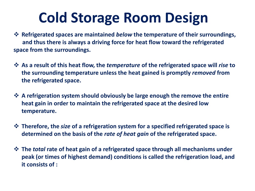
Cold Storage Room Design Refrigerated spaces are maintained below the temperature of their surroundings, and thus there is always a driving force for heat flow toward the refrigerated space from the surroundings. As a result of this heat flow, the temperature of the refrigerated space will rise to the surrounding temperature unless the heat gained is promptly removed from the refrigerated space. A refrigeration system should obviously be large enough the remove the entire heat gain in order to maintain the refrigerated space at the desired low temperature. Therefore, the size of a refrigeration system for a specified refrigerated space is determined on the basis of the rate of heat gain of the refrigerated space. The total rate of heat gain of a refrigerated space through all mechanisms under peak (or times of highest demand) conditions is called the refrigeration load, and it consists of :
transmission load, which is heat conducted into the refrigerated space through its walls, floor, and ceiling; infiltration load, which is due to surrounding warm air entering the refrigerated space through the cracks and open doors; product load, which is the heat removed from the food products as they are cooled to refrigeration temperature; internal load, which is heat generated by the lights, electric motors, and people in the refrigerated space; and refrigeration equipment load, which is the heat generated by the refrigeration equipment as it performs certain tasks such as reheating and defrosting The size of the refrigeration equipment must be based on peak refrigeration load, which usually occurs when the outside temperature is high and the maximum amount of products is brought into the cool storage room at field temperatures.
Transmission Load The transmission load depends on the materials and construction of the walls, floor, and ceiling of the refrigerated space, the surface area, the air motion or wind conditions inside or outside, and the temperature difference between the refrigerated space and the ambient air. The rate of heat transfer through a particular wall, floor, or ceiling section can be determined from Qtransmission = UAo T where, Ao= outside surface area of the section, T = temperature difference between the outside air and the air inside the refrigerated space, U = overall heat transfer coefficient Figure showing various mechanisms of heat gain that make up the total refrigeration load of a refrigerated space.
Noting that the thickness-to-thermal-conductivity ratio of a layer represents its unit thermal resistance, the overall heat transfer coefficient is determined from : where hi =heat transfer coefficient at the inner surface of the refrigerated space ho=heat transfer coefficient at the outer surface of the refrigerated space L/k = sum of the thickness-to-thermal-conductivity ratios of the layers that make up the section under consideration Figure showing the determination of thermal resistance and the overall heat transfer coefficient for a two-layer wall section for the calculation of transmission losses.
For still air, it is common practice to take 10 W/m2 o C for hi and ho. A value of 20 or 30 W/m2 oC can be used for hofor low or moderate wind conditions outside, respectively. The walls, floor, and ceiling of typical refrigerated rooms are well insulated, and the unit thermal resistance L/k of the insulation layer is usually much larger than the L/k of other layers such as the sheet metals and the convective resistance 1/hiand 1/ho. Therefore, the thermal resistances of sheet metal layers can always be ignored. Also, the convection resistances 1/hi and 1/ho are often negligible, and thus having very accurate values of hi and ho is usually not necessary. When constructing refrigerated rooms, it is desirable to use effective insulation materials to minimize the refrigerated space for a fixed floor area. Minimum insulation thicknesses for expanded polyurethane (k 0.023 W/m oC) recommended by the refrigeration industry are given in Table below. Note that the larger the temperature difference between the refrigerated space and the ambient air, the thicker the insulation required to reduce the transmission heat gain to reasonable levels.
Table, showing minimum recommended expanded polyurethane insulation thicknesses for refrigerated rooms. Equivalent thicknesses for other insulating materials can be obtained by multiplying the values in this table by kins/kpoly where kinsand kpolyare the thermal conductivities of the insulation material and the polyurethane, respectively. Direct exposure to the sun increases the refrigeration load of a refrigerated room as a result of the solar energy absorbed by the outer surface being conducted into the refrigerated space. The effect of solar heating can conveniently be accounted for by adding a few degrees to the ambient temperature. For example, the solar heating effect can be compensated for, by adding 4oC to the ambient temperature for the east and west walls, 3oC for the south walls, and 9oC for flat rooms with medium-colored surfaces such as unpainted wood, brick, and dark cement. (See Figure below) For dark- (or light-) colored surfaces, we should add (or subtract) to 1oC (or from) these values.
Figure showing solar heating effect on the west or east wall can be compensated for, by adding 4oC to the ambient temperature.
Infiltration Load The heat gain due to the surrounding warm air entering the refrigerated space through the cracks and the open doors continues the infiltration load of the refrigeration system (See Figure). The infiltration load changes with time. We should consider the maximum value to properly size the refrigeration system, and the average value to properly estimate the average energy consumption. In installations that require the doors to remain open for long periods of time, such as distribution warehouses, the infiltration load may amount to more than half of the total refrigeration load. In the absence of any winds, the infiltration is due to the density difference between the cold air in the refrigerated space and the surrounding warmer air. When the average velocity of the air entering the refrigerated space under the influenceof winds or pressure differentials is known, the rate of infiltration heat gain can be determined from:
Qinfiltration windy air =6VairAleakCp,air(Twarm - Tcold)coldDtime , where Vair= average air velocity, usually between 0.3 and 1.5 m/s Aleak= smaller of the inflow or outflow opening areas, m2 cp, air = specific heat of air, 1.0 kJ/kg C Twarm= temperature of the warm infiltration air, oC Tcold= temperature of the cold infiltration air, oC cold= density of the cold refrigerated air, kg/m3 Dtime = density open-time factor. There is considerable uncertainty in the determination of the infiltration load, and field experience from similar installations can be a valuable aid in calculations. A practical way of determining the infiltration load is to estimate the rate of air infiltration in terms of air changes per hour (ACH), which is the number of times tire entire air content of a room is replaced by the infiltrating air per hour.
Once the number of air changes per hour is estimated, the mass flow rate of air infiltrating into the room is determined from: mair =(Vroom/ vair )ACH (kg/h) where Vroomis the volume of the room and vairis the specific volume of the dry air in the room. Once mair is available, the infiltration load of the cold storage room can be determined from: Q infiltration= mair(hambient- hroom) ( kJ/h) Where, h is the enthalpy of air. The values of specific volume v, and enthalpy h, can be determined from the psychrometric chart when the temperature and relative humidity (or wet-bulb temperature) of air are specified. The value of ACH should be determined under the most adverse operating conditions (such as during loading or unloading and high winds) to ensure satisfactory performance under those conditions.
Product Load The heat removed from the food products as they are cooled to refrigeration temperature and the heat released as the fresh fruits and vegetables respire in storage constitute the product load of the refrigeration system (See Figure). As we mentioned earlier, the refrigeration of foods involves cooling only, but the freezing of foods involves cooling to the freezing point (removing the sensible heat), freezing (removing the latent heat), and further cooling to the desired subfreezing temperature (removing the sensible heat of frozen food). The three components of the product load can be determined from Qcooling, fresh = mcp,fresh(T1 - Tfreeze) (kJ) Qfreezing = mhlatent (kJ) Qcooling, frozen = mcp, frozen(Tfreeze -T2) (kJ) where, m =mass of the food product, cp, fresh= specific heat of the food before freezing, cp, frozen = specific heat of the food after freezing hlatent= latent heat of fusion of the food, Tfreeze=freezing temperature of the food , T1= initial temperature of the food (before refrigeration) T2= final temperature of the food (after freezing)
The rate of refrigeration needed to cool a product from T1to T2during a time interval t can be determined from: Note that it will take a relatively short time for a powerful refrigeration system to accomplish the desired cooling. Food products are usually refrigerated in their containers, and the product load also includes cooling the containers. The amount of heat that needs to be removed from the container as it is cooled from T1to T2 can be determined from: Qcontainer= mcp container(T1-T2) (kJ) where m is the mass of the container and cp, container is the specific heat of the container, which is 0.50 kJ/kg oC for stainless steel, 1.7 kJ/kg oC for nylon, 1.9 kJ/kg oC for polypropylene, and 2.3 kJ/kg oC for polyethylene containers. The contribution of Q containerto the refrigeration load is usually very small and can be neglected.
Internal Load The heat generated by the people, lights, electric motors, and other heat- dissipating equipment in the refrigerated space constitutes the internal load of the refrigeration system (See Figure) The rate of heat dissipation by people depends on the size of the person, the temperature of the refrigerated space, the activity level, and the clothing, among other things. A person must generate more heat at lower temperatures to compensate for the increased rate of heat transfer at higher temperature differences. The heat dissipated by an average person in a refrigerated space maintained at temperature T in C is expressed as :
Qpeople=270-6T(oC) (W/person) An average person, for example, will dissipate 210 W of heat in a space maintained at 10C and 360 W in a space at -15C. The rate of heat dissipation from lights is determined by simply adding the wattage of the light bulbs and the fluorescent tubes. For example, five 100-W incandescent light bulbs and eight 40-W fluorescent tubes contribute 820 W to the refrigeration load when they all are on. The calculation of the heat dissipation from the motors is more complicated because of the uncertainties involved in the operation such as the motor efficiency, the load factor (the fraction of the rated load at which the motor normally operates), and the utilization factor (the fraction of the time during which the motor actually runs), and whether the motor running a device such as a fan is located inside the refrigerated space. Noting that the motors are usually oversized, the rated power of a motor listed on its tag tells us little about its contribution to the refrigeration load.
When the body of a motor-running a device is housed outside the refrigerated space, then the internal heat load of this motor is simply the power consumed by the device in the refrigerated space. When the motor is housed inside the refrigerated space, then the heat dissipated by the motor also becomes part of the internal heat load since this heat now must be removed from the refrigeration system. Keeping the motors inside the refrigerated space may increase the internal load due to motors by 30 to 80 percent. Refrigeration Equipment Load The refrigeration equipment load refers to the heat generated by the refrigeration equipment itself as it performs certain tasks such as circulating the cold air with a fan, electric reheating to prevent condensation on the surfaces of the refrigerator, and defrosting to prevent frost build-up and to evaporate moisture. Equipment load can be as little as 5 percent of the total refrigeration load for simple refrigeration systems or it may exceed 15 percent for systems maintained at very low temperatures.
When the total refrigeration load is determined as described above, it is common practice to apply a safety factor of 10 percent to serve as a cushion to cover any unexpected situations. EXAMPLE : Freezing of Chicken A supply of 50 kg of chicken at 6C contained in a box is to be frozen to 18 oC in a freezer. Determine the amount of heat that needs to be removed. The container box is 1.5 kg, and the specific heat of the box material is 1.4 kJ/kg oC. Assumption: The entire water content of chicken freezes during the process. For chicken, the freezing temperature is -2.8oC, the latent heat of fusion is 247 kJ/kg, the specific heat is 3.32 kJ/kg oC above freezing and 1.77 kJ/kg oC below freezing The total amount of heat that needs to be removed (the cooling load of the freezer) is the sum of the latent heat and the sensible heats of the chicken before and after freezing as well as the sensible heat of the box, and is deter mined as follows:
Cooling fresh chicken from 6 oC to -2.8 oC: Qcooling, fresh =(mcp T)fresh =(50 kg)(3.32 kJ/kg oC)[6 - (-2.8)]C =1461 kJ Freezing chicken at -2.8 oC: Qfreezing =m hlatent =(50 kg)(247 kJ/kg) =12,350 kJ Cooling frozen chicken from -2.8 oC to -18 oC: Qcooling, frozen =(mcp T)frozen= (50 kg)(1.77 kJ/kg .oC)[-2.8 (-18)]oC =1345 kJ Cooling the box from 6oC to -18 o C: Qbox =(mcp T)box =(1.5 kg)(1.4 kJ/kg oC)[6 -(-18)]oC = 50 kJ Therefore, the total amount of cooling that needs to be done is: Qtotal = Qcooling, fresh + Qfreezing + Qcooling, frozen Qbox 1461+12,350 +1345 +50 =15,206 kJ DISCUSSION Note that most of the cooling load (81 percent of it) is due to the removal of the latent heat during the phase change process. Also note that the cooling load due to the box is negligible (less than 1 percent), and can be ignored in calculations.
EXAMPLE: Infiltration Load of Cold Storage Rooms A cold storage room whose internal dimensions are 3 m x6 m x10 m is maintained at 1oC and 95 percent relative humidity (See Figure). Under worst conditions, the amount of air infiltration is estimated to be 0.2 air changes per hour at the ambient conditions of 30oC and 90 percent relative humidity. Using the psychrometric chart, determine the total infiltration load of this room under these conditions. Solution: The heat of vaporization of water at the average temperature 15 oC is 2466 kJ/kg . The properties of the cold air in the room and the ambient air are determined from the psychrometric chart to be: At Tambient =30 oC, and 90 % RH ambient=0.024 kgmoisture/kg dry air hambient=93 kJ/kg dry air At Troom=1oC and 95% RH room=0.0384 kg/kg dry air hroom=11 kJ/kg dry air vroom = 0.78 m3/kg dry air
Noting that the infiltration of ambient air will cause the air in the cold storage room to be changed 0.2 times every hour, the air will enter the room at a mass flow rate of: Then, the infiltration heat gain of the room become: Qinfiltration = mair(hambient - hroom)= (0.0128 kg/s)(93 -11)kJ/kg =1.05 kW That is, the refrigeration system of this cold storage room must be capable of removing heat at a rate of 1.05 kJ/s to meet the infiltration load. Of course, the total refrigeration capacity of the system will have to be larger to meet the transmission, product, and other loads as well.
TRANSPORTATION OF REFRIGERATED FOODS Perishable food products are transported by trucks and trailers, railroad cars, ships, airplanes, or a combination of them from production areas to distant markets. Transporting some farm products to a nearby market by a small truck may not require any special handling, but transporting large quantities over long distances usually requires strict climate control by refrigeration and adequate ventilation . See Figure. Refrigerated trucks and trailers can be up to 17 m long, 2.6 m wide, and 4.3 m high, and they may have several compartments held at different temperatures. The body of the truck should be lightweight but stiff with good insulating characteristics.
Using a thick insulation layer on walls reduces the rate heat gain into the refrigerated space, but it also reduces the available cargo space since the outer dimensions of the trucks and trailers are limited. Urethane foam is commonly used as an insulating material because of its low thermal conductivity (k = 0.026 W/m oC). The thickness of polyurethane insulation used is in the range of 7.5 to 10 cm for freezer trucks maintained at -18 o C or lower, and 2.5 to 6.5 cm for refrigerated trucks maintained above freezing temperatures as shown below. The outer surface of the truck must be vapor proof to prevent water vapor from entering the insulation and condensing within the insulation. Air entering inside the refrigerated space of the truck through cracks represents a significant heat gain since the moisture in the air will be cooled inside and condensed, releasing its latent heat.
The large temperature difference between the ambient air and the interior of the refrigerated truck serves as a driving force for air infiltration. Air leakage is also caused by the ram effect of air during motion. It can be shown from Bernoulli s equation that a truck moving at a velocity of V will generate a ram air pressure of P = V2/2 at the front section ( is the density of air). This corresponds to a pressure rise of about 300 Pa on the surface of the truck at a velocity of 80 km/h. Road tests have shown that air leakage rates for large trailers can reach 12.5 L/s at 80 km/h. Further, the water vapor in the air that condenses inside the refrigerated space may cause corrosion, damage to insulation, rotting, and odors. Products with a large heat capacity such as milk and orange juice can be transported safely without refrigeration by subcooling them before loading into the truck. For example, orange juice shipped from Florida to New York (a distance of 2300 km) warmed up only 5 oC without any refrigeration. Liquid nitrogen, dry ice, or ordinary ice can also be used for refrigeration in trucks.
The cargo space must be maintained at -18 oC for most frozen products and -29 oC for other deep-frozen products such as ice cream. The rate of heat gain by properly insulated trailers that are 11 to 16 m long ranges from 40 to 130 W/C under steady conditions. But on a sunny day the solar radiation can increase this number by more than 20 percent. The rate of heat gain can also increase significantly as a result of the product cooling load, air infiltration, and opening of the door during loading and unloading. The interior of refrigerated trucks should be precooled to the desired temperature before loading. The fruits and vegetables should also be cooled to the proper storage temperature before they are loaded into the refrigerated railcars or trucks. This is because the refrigerated cars or trucks do not have the additional refrigeration capacity to cool the products fast enough. Also, the products must be protected from freezing in winter. Refrigerated cars or trucks provide heating in cold weather by electric heating or by operating the refrigeration system in reverse as a heat pump. Switching from cooling to heating is done automatically.
The heating and cooling processes in refrigerated cars and trucks are well automated, and all the operator needs to do is set the thermostat at the desired level. The system then provides the necessary refrigeration (or healing in cold weather) to maintain the interior at the set temperature. Thermostats must be calibrated regularly to ensure reliable operation since a deviation of a few degrees from the intended temperature setting may cause the products to be damaged by freezing or excessive decay. Food products are normally loaded into cars or trucks in containers that can be handled by people or forklifts. The containers must allow for heat exchange while protecting the products. The containers must allow for air circulation through channels for uniform and effective cooling and ventilation. The railroad industry also provides refrigerated car service for the transportation of perishable foods. The walls, floors, and ceiling of the cars are constructed with a minimum of 7.5-cm-thick insulation. Typical rates of heat gain are 132 W/C for 15-m-long cars and 158 W/C for 18-m-long cars
