Understanding RC Circuits in DC Circuits
Learn about RC circuits in DC circuits, where resistors and capacitors work together to control the flow of current and voltage. Explore the behavior of capacitors during charging and discharging, the role of time constants, and how to calculate key parameters in RC circuits.

Download Presentation

Please find below an Image/Link to download the presentation.
The content on the website is provided AS IS for your information and personal use only. It may not be sold, licensed, or shared on other websites without obtaining consent from the author. If you encounter any issues during the download, it is possible that the publisher has removed the file from their server.
You are allowed to download the files provided on this website for personal or commercial use, subject to the condition that they are used lawfully. All files are the property of their respective owners.
The content on the website is provided AS IS for your information and personal use only. It may not be sold, licensed, or shared on other websites without obtaining consent from the author.
E N D
Presentation Transcript
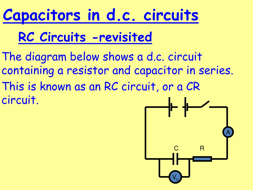
Capacitors in d.c. circuits RC Circuits -revisited The diagram below shows a d.c. circuit containing a resistor and capacitor in series. This is known as an RC circuit, or a CR circuit. A C R Vc
Charging Capacitors p.d. (V) Current (A) Vs Time Time 0 0 In a d.c. circuit, when a capacitor is fully charged, the voltage across the capacitor rises up to the supply voltage and no more current flows. The capacitor BLOCKS d.c.
Discharging Capacitors Current (A) p.d. (V) 0 Time Time 0 The current during discharge is in the opposite direction to the charging current hence graph appears below x-axis.
Time RC circuits As can be seen from the graphs there is a factor of time involved in the capacitor reaching a fully charged or discharged state. The bigger the value of resistance the lower the current and the longer it takes to become fully charged and vice-versa. The bigger value of capacitance the longer it will take for the capacitor to fully charge. (A bigger bucket takes longer to fill than a smaller one).
p.d. (V) Smaller capacitor and/or resistor Current (A) Smaller resistor Larger capacitor and/or resistor Larger resistor Time Time 0 0
Time constant The RC time constant is t = RC Where: R is in ohms ( ) C is in farads (F) t is in seconds (s) It is defined as the time to increase the charge stored by 63% (0.63) of the difference between initial charge and full charge, or the time taken to discharge the capacitor to 37% (0.37) of initial charge. Do not copy but try this: Do an analysis of the units to show that ohms multiplied by farads gives seconds.
If the charging current stayed constant then the capacitor would charge in the time given by RC but as the current decreases during charging, the p.d. across the capacitor only reaches 0.63 of the supply after one time constant has passed. Similarly, the charging current reaches 37% (0.37) of it s initial value after one time constant.
Example: 9.0V 2.0k 10.0 F A 10.0 F capacitor is charged in series with a 2.0k resistor using a 9.0V supply. Calculate a) the time constant for this circuit. Answer: b) What is the p.d. across the capacitor after 0.040 seconds.