Understanding Digital Gates and Boolean Algebra Basics
Explore the fundamental concepts of digital gates and Boolean algebra, including the representation of logical values, gate functions, transistor behavior, gate symbols, truth tables, and the simplicity of NOT, NAND, and NOR gates. Gain insights into the number of transistors required per gate and the possibilities in Boolean functions. Dive into the world of two-valued signals, gate functions, and the primary gates NOT, NAND, NOR, AND, and OR.

Download Presentation

Please find below an Image/Link to download the presentation.
The content on the website is provided AS IS for your information and personal use only. It may not be sold, licensed, or shared on other websites without obtaining consent from the author. If you encounter any issues during the download, it is possible that the publisher has removed the file from their server.
You are allowed to download the files provided on this website for personal or commercial use, subject to the condition that they are used lawfully. All files are the property of their respective owners.
The content on the website is provided AS IS for your information and personal use only. It may not be sold, licensed, or shared on other websites without obtaining consent from the author.
E N D
Presentation Transcript
Gates and Boolean Algebra Ch 3.1
Gates Digital circuit is one in which only two logical values are present Different values represented by varying signals Signal between 0 and 0.5 volts (often binary/logical 0) Signal between 1 and 1.5 volts (often binary/logical 1) Voltages outside those ranges not permitted Gates: tiny electronic devices that compute various functions of these two-valued signals Form the hardwire basis on which all digital computers are built Details of how gates work inside is the device level: beyond our scope (below our level 0) 2
Gates at the device level very briefly Input (Vin, or V1, V2) & output voltage (Vout) When input voltage is low (below a certain critical value) transistor turns off and acts like an infinite resistance Vout is high: takes on value close to Vcc (typically +1.5 volts -- logical 1) When input voltage is high (exceeds critical value) transistor switches on and acts like a wire Vout is low: pulled down to ground (0 volts -- logical 0) Output is 0 iff both inputs are 1 Converts logical 0 into logical 1, and vice versa Output is 1 iff both inputs are 0 3 (a) A transistor inverter. (b) A NAND gate. (c) A NOR gate.
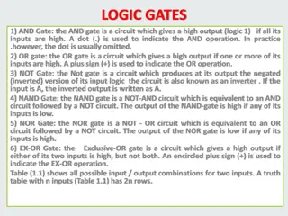
The three simplest gates: NOT, NAND, NOR We will represent gates as symbols Small circles in the gate are called inversion bubbles Gate symbols: Boolean function: (described by a truth table) 4
Two additional gates: AND, OR We will represent gates as symbols Small circles in the gate are called inversion bubbles Gate symbols (top) Boolean function (bottom - described by a truth table) 5
Two additional gates: AND, OR We will represent gates as symbols Small circles in the gate are called inversion bubbles Gate symbols (top) Boolean function (bottom - described by a truth table) Q: How many transistors does each gate require? 6
Boolean algebra Variables and functions can take on only the values 0 and 1 Ex: Boolean function f is defined as f(A) = 1 if A is 0, and f(A) = 0 if A is 1. NOT function How many possible combinations of input values are possible in a Boolean function of n variables? 7
Boolean algebra Variables and functions can take on only the values 0 and 1 Ex: Boolean function f is defined as f(A) = 1 if A is 0, and f(A) = 0 if A is 1. NOT function How many possible combinations of input values are possible in a Boolean function of n variables? 2? Truth table: A way of completely describing a Boolean function by giving a table with 2? rows, each row telling the value of the function for a different combination of input values. List rows in ascending numerical order (base 2) First row: all 0s Last row: all 1s We can describe a function by reading the result column of the truth table vertically. Ex: NAND is 1110 8
Boolean function notation Suppose there is one inputs to a function f, which we will call A. The NOT function can be described as ? = ? Suppose there are two inputs to a function f, which we will call A and B. The OR function can be described as ? = ? + ? The AND function can be described as ? = ?? 9
Boolean function notation Suppose there is one inputs to a function f, which we will call A. The NOT function can be described as ? = ? Suppose there are two inputs to a function f, which we will call A and B. The OR function can be described as ? = ? + ? The AND function can be described as ? = ?? Here, we have a function f with three inputs A,B,C. This is the majority logic function, i.e., it is 0 if a majority of its inputs are 0, and It is 1 if a majority of its inputs are 1 We could describe this function by: 1) its truth table, or 2) the following compact representation: ? = ??? + ??? + ??? + ??? 10
Constructing a circuit for a function Input: a Boolean function (majority function of 3 variables) as described in the following truth table. Goal: Draw a circuit that accomplishes this using only AND, OR, and NOT gates. 11 ? = ??? + ??? + ??? + ???
Constructing a circuit for a function Input: a Boolean function (majority function of 3 variables) as described in the following truth table. Goal: Draw a circuit that accomplishes this using only AND, OR, and NOT gates. 12 ? = ??? + ??? + ??? + ???
Circuit implementation We have a general method to implement a circuit for any Boolean function: Write truth table for function Provide inverters to generate complement of each input Draw AND gate for each term with 1 in result column Wire AND gates to appropriate inputs Feed output of all AND gates into an OR gate Example: Implement a circuit for Boolean function f which takes three inputs, A, B, C, and outputs a 1 iff no more than one of the inputs is a 1.
Ex: Circuit implementation Example: Implement a circuit for Boolean function f which takes three inputs, A, B, C, and outputs a 1 iff no more than one of the inputs is a 1.
Working towards a better circuit implementation New goal: Construct a circuit with less gates Reduce chip area needed to implement them Minimize power consumption Increase speed Our previous approach guarantees we CAN construct a circuit Solution is feasible Doesn t necessarily construct one using only a few gates A functionally complete set of gates is one which can be used to expressall possible truth tables by combining members of the set into a Boolean expression. {NOT, AND, OR} is functionally complete. {NAND} is functionally complete. {NOR} is functionally complete. It s often convenient to implement circuits using only a single type of gate Ex: any Boolean function can be computed using just NAND gates! (or just NOR gates!)
Circuit equivalence: NOT, AND, and OR using only NAND gates Which one is which? only NAND gates
Circuit equivalence: NOT, AND, and OR using only NOR gates Which one is which? only NOR gates
Two circuits/functions are equivalent if and only if they have the same output for every possible input. Circuit Equivalence Goal: Design a circuit using a small number of gates Reduces chip area needed Minimizes power consumption Increases speed Example: Can you find a circuit which uses less gates but is equivalent to the circuit on the right? Note: Use a truth table to prove equivalence.
Examples 1. Build a circuit for XOR. Can you build it in more than one way? 2. Use a truth table to show that X = (X AND Y) OR (X AND NOT Y)
Note on equivalence: Positive vs. Negative logic The same physical gate can compute different functions, depending on the convention used. Positive logic: (we assume this) low voltage = logical 0 / false high voltage = logical 1 / true Negative logic: low voltage = logical 1 / true high voltage = logical 0 / false Electrical characteristics of a device Positive logic Negative logic
Example circuit: Half-Adder (Fig 3-16) Goal: Add A+B Output: Sum and Carry Truth table for 1-bit addition. A circuit for a half adder. 23


")