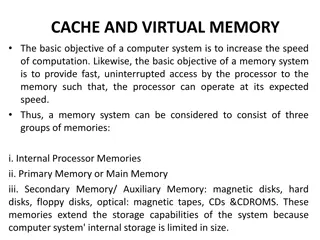
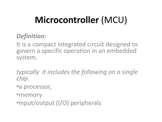
Understanding Different Types of Memory in MSP430 Microcontrollers

MSP430 memory includes volatile RAM, dynamic RAM, nonvolatile ROM, EPROM, and flash memory. Each type has unique characteristics such as data retention, ease of read/write, cost implications, and methods of programming and erasing. Microcontrollers utilize various memory types based on requirements for data storage, retrieval, and program execution. The Harvard Architecture is also discussed, highlighting separate systems for volatile and nonvolatile memories to enhance efficiency and performance.

Download Presentation

Please find below an Image/Link to download the presentation.
The content on the website is provided AS IS for your information and personal use only. It may not be sold, licensed, or shared on other websites without obtaining consent from the author. Download presentation by click this link. If you encounter any issues during the download, it is possible that the publisher has removed the file from their server.
E N D
Presentation Transcript
UNIT-III MSP 430 Memory Volatile Memory: Loses its contents when power is removed. It is usually called random-access memory or RAM. The vital feature is that data can be read or written with equal ease. Volatile memory is used for data, and small microcontrollers often have very little RAM, sometimes only a few tens of bytes. Static RAM: means that it retains its data even if the clock is stopped (provided that power is maintained, of course). A single cell of static RAM needs six transistors. RAM therefore takes up a large area of silicon, which makes it expensive. V SUPRAJA 1
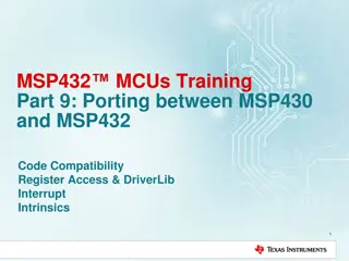
Dynamic RAM: This needs only one transistor per cell but must be refreshed regularly to maintain its contents, so it is not used in small microcontrollers. Most memory in a desktop computer is dynamic RAM. Nonvolatile Memory: Retains its contents when power is removed and is therefore used for the program and constant data. It is usually called read-only memory or ROM There are many types of nonvolatile memory in use: Masked ROM: The data are encoded into one of the masks used for photolithography and written into the IC during manufacture. This memory really is read-only. V SUPRAJA 2
It is used for the high-volume production of stable products, because any change to the data requires a new mask to be produced at great expense. Some MSP430 devices can be ordered with ROM, shown by a C in their part number. An example is the MSP430CG4619. EPROM (electrically programmable ROM): As its name implies, it can be programmed electrically but not erased. Devices must be exposed to ultraviolet (UV) light for about ten minutes to erase them. erasable devices need special packages with quartz windows, which are expensive. V SUPRAJA 3
Flash memory: This can be both programmed and erased electrically and is now by far the most common type of memory. The practical difference is that individual bytes of EEPROM can be erased but flash can be erased only in blocks. Most MSP430 devices use flash memory, shown by an F in the part number. Microcontrollers use NOR flash, which is slower to write but permits random access. NAND flash is used in bulk storage devices and can be accessed only serially in rows. V SUPRAJA 4
Harvard and Von-Neuman Architectures Block Diagram: V SUPRAJA 5
Harvard Architecture: The volatile (data) and nonvolatile (program) memories are treated as separate systems. Each with its own address and data bus. Many microcontrollers use this architecture, including Microchip PICs, the Intel 8051 and descendents, and the ARM9. The principal advantage is efficiency. It allows simultaneous access to the program and data memories. For instance, the CPU can read an operand from the data memory at the same time as it reads the next instruction from the program memory. Easier to pipeline so high performance can be achieved. No memory alignment problems. High Cost V SUPRAJA 6
von Neumann Architecture: Single shared bus for instruction and data fetching. There is only a single memory system in the von Neumann or Princeton architecture. This means that only one set of addresses covers both the volatile and nonvolatile memories. The architecture is intrinsically less efficient because several memory cycles may be needed to extract a full instruction from memory. Low performance compared to Harvard architecture. It has memory alignment problems. Cheaper Microcontrollers with a von Neumann architecture include the MSP430, the Freescale HCS08, and the ARM7. V SUPRAJA 7
RISC vs CISC RISC CISC Reduced Instruction set Computer Complex Instruction set Computer Less number of instructions More number of instructions It uses instruction pipelining feature. So, the execution speed is more. No instruction pipelining feature. Orthogonal instruction set. Non Orthogonal instruction set Operations are performed on registers only, the only memory operations are load and store. Operations are performed on registers or memory depending on the instruction. Large number of registers are available Limited number of general purpose registers Programmer need to write more code to execute task since instructions are simple ones Instructions are like macros in C language. Programmer can achieve the desired functionality with single instructions. V SUPRAJA 8
Single and fixed length instructions. Variable length instructions Less silicon usage and pin count More silicon usage It uses harvard or von- neumann architecture. It uses harvard or von- neumann architecture. Eg: Atmel AVR contains 32 instructions Eg: Atmel AT89C51 contains 255 instructions. V SUPRAJA 9
INTRODUCTION TO MSP430 MICROCONTROLLERS The MSP430 was introduced in the late 1990s 16bit processor with a vonNeumann architecture, designed for low-power applications The CPU is often described as a reduced instruction set computer (RISC) The registers in the CPU are also all 16 bits wide and can be used interchangeably for either data or addresses The MSP430 has 16registers in its CPU, which enhanc es efficiency because they can be used for local variables, parameters passed to subroutines, and eith er addresses or data V SUPRAJA 10
Several features make the MSP430 suitable for low- power and portable applications: The CPU is small and efficient, with a large number of registers It is extremely easy to put the device into a low- power mode. No special instruction is needed The crystal runs continuously at 32KHz and is used to wake the device periodically. MSP430 can wake from a stand by mode rapidly, perform its tasks, and return to a low- power mode A wide range of peripherals is available, many of wh ich can run autonomously without the CPU for most of the time V SUPRAJA 11
Many portable devices include liquid crystal displays which the MSP430 can drive directly. MSP430 Family: The letter after MSP430 shows the type of memory. F Flash memory, C for ROM The second letter shows ASIP. E for Electricity, W for water, G for signals that require a gain stage. The next digit shows the family and the final two or three digits identify the specific device MSP430x1xx: Provides a wide range of general purpose devices from simple versions to complete systems for processing signals V SUPRAJA 12
There is a broad selection of peripherals and some include a hardware multiplier, which can be used as rudimentary digital signal processor Packages have 20 64 pins MSP430F2xx: Introduced in 2005. CPU can run at16 MHz, double the speed of earlier devices, while consuming only half the current at the same speed. 14 pin PDIP package . Pull-up or pull down resistors are provided on the inputs to reduce the number of external components needed V SUPRAJA 13
Even the smallest,14-pin devices offer a 16- bit sigma delta ADC. MSP430x3xx: The original family, which includes drivers for LCDs. It i s now obsolescent. MSP430x4xx: Can drive LCDs with up to 160 segments. Many of th em are ASSPs, but there are general- purpose devices as well. Their packages have 48 113 pins, many of which are needed for the LCD. V SUPRAJA 14
MSP430F2003 and F2013 Pin Diagram V SUPRAJA 15
MSP430F2003 and F2013 Pin Diagram VCC and VSS , P1.0 P1.7, P2.6, and P2.7 , TACLK, TA0, and TA1 are associated with Timer_A; A0 , A0+, and so on, up to A4 , are inputs to the anal og-to-digital converter. ACLK and SMCLK are outputs for the microcontroller s clock signals SCLK, SDO, and SCL are used for the universal serial in terface XIN and XOUT , RST, NMI TCK, TMS, TCLK, TDI, TDO, and TEST form the full JTAG in terface, used to program and debug the device SBWTDIO and SBWTCK provide the Spy-Bi- Wire interface, an alternative to the usual JTAG connection that saves pins V SUPRAJA 16
Key Features of MSP430 a low power Microcontroller released by Texas Instruments in the late 1990s. a 16-bit RISC based mixed signal processor. with a set of intelligent peripherals like I/O, Timers ADC, DAC, flexible clock and USCI low cost lowest power consumption Ultra low power optimization extends battery life multiple low power modes of operation V SUPRAJA 17
Contd.. Extensive interrupt capability relieves need for polling Prioritized nested interrupts Seven source-address modes Four destination-address modes Only 27 core instructions and 24 Emulated Instructions Large register file Efficient table processing Fast hex-to-decimal conversion V SUPRAJA 18
contd.. MSP430 requires 0.1 A for RAM data Retention, 0.8 A for RTC mode operation 250 A /MIPS for active mode operation. Low operation voltage (from 1.8 V to 3.6 V). Zero-power Brown-Out -Reset (BOR) V SUPRAJA 19
V SUPRAJA 20
MEMORY The MSP430X extends the range of memory by a factor of 16 to 20 bytes by adding a further 4 bits to the address bus and the registers in the CPU. Byte accessing and Word accessing. Two bytes at 0x0200 and 0x0201 can be considered as a valid word with address 0x0200 V SUPRAJA 21
Hexadecimal value 0x1234 Little-endian ordering: The low- order byte is stored at the lower address and the Higherorder byte at the higher address. This is used byte MSP430 and is the more common format. Big-endian ordering: The high- order byte is stored at the lower address. This is use dby the Freescale HCS08. Addresses increase from left to right across each line. This means that the low-order byte is displayed first, followed by the high-order byte. Thus our value of 0x1234 is displayed as 34 12. V SUPRAJA 22
V SUPRAJA 23
MSP430 CPU The CPU of MSP 430 includes a 16-bit ALU and a set of 16 Registers R0 R15.In these registers Four are special Purpose and 12 are general purpose registers . All the registers can be addressed in the same way. The special Purpose Registers are PC (Program Counter), SP (Stack Pointer) , SR (Status Register) and CGx (Constant Generator) V SUPRAJA 24
Registers in the CPU of the MSP430 V SUPRAJA 25
The MSP430 CPU includes an arithmetic logic unit (ALU) that handles addition, subtraction, comparison and logical (AND, XOR) operations. ALU operations can affect the overflow, zero, negative, and carry flags in the status register. R0: Program Counter (PC) The 16-bit Program Counter (PC/R0) points to the next instruction to be read from memory and executed by the CPU. The Program counter is incremented by 2. It is important to note that the PC is aligned at even addresses, because the instructions are 16 bits, even though the individual memory addresses contain 8-bit values. Subroutines and interrupts also modify the PC but in these cases the previous value is saved on the stack and restored later V SUPRAJA 26
R1: Stack Pointer (SP) The Stack Pointer (SP/R1) is located in R1. Stack can be used by user to store data for later use(instructions: store by PUSH, retrieve by POP) Stack is also heavily used for temporary variables, passing parameters to subroutines and returning the result. The stack is allocated at top of RAM and grows down towards the low address. SP holds the address of top of the stack. V SUPRAJA 27
V SUPRAJA 28
Contd.. For programs written in C, the compiler initializes the stack automatically as part of the startup code, which runs silently before the program starts, but you must initialize SP yourself in assembly language. V SUPRAJA 29
R2: Status Register (SR) The Status Register (SR/R2) is a 16 bit register , and it stores the state and control bits. The system flags are changed automatically by the CPU depending on the result of an operation in a register. The reserved bits of the SR are used to support the constants generator. V SUPRAJA 30
The hexadecimal sum 0x75+0xC7=0x13C, where the result is too large to be held in a single byte The zero flag Z is set when the result of an operation is 0. The negative flag N is made equal to the msb of the result, which indicates a negative number if the values are signed. The signed over low flag V is set when the result of a signed operation has overflowed, even though a carry may not be generated Remember that a byte can hold the values 0 to 0xFF if it is unsigned or 0x80 to 0x7F if it is signed. V SUPRAJA 31
MSP430 CPU block diagram V SUPRAJA 32
Enable Interrupts Setting the general interrupt enable or GIE bit enables maskable interrupts, provided that the individual sources of interrupts have themselves been enabled. Clearing the bit disables all maskable interrupts. Control of Low-Power Modes The CPUOFF, OSCOFF, SCG0, and SCG1 bits control the mode of operation of the MCU. All systems are fully operational when all bits are clear. Setting combinations of these bits puts the device into one of its low-power modes. V SUPRAJA 33
R2/R3: Constant Generator Registers (CG1/CG2) Depending on the source-register addressing modes (As) value, six commonly used constants can be generated without a code word or code memory access to retrieve them. This is a very powerful feature, which allows the implementation of emulated instructions, for example, implementing a core instruction for an increment, the constant generator is used. instead of V SUPRAJA 34
R4 - R15: GeneralPurpose Registers These general-purpose registers are used to store data values , address pointers, or index values and can be accessed with byte or word instructions. V SUPRAJA 35
Addressing modes The MSP430 supports seven addressing modes for the source operand and four addressing modes for the destination operand . They are Register mode Indexed mode Symbolic mode Absolute mode Indirect register mode Indirect auto incr ment mode Immediate mode V SUPRAJA 36
Register Mode Register mode operations work directly on the processor registers, R4 through R15, or on special function registers, such as the program counter or status register. They are very efficient in terms of both instruction speed and code space. Ex : MOV.b R4, R5 MOV.W R4,R5 Move (copy) the contents of source (register R4) to destination (register R5). Register R4 is not affected. V SUPRAJA 37
Indexed mode The Indexed mode commands are formatted as X(Rn), where X is a constant and Rn is one of the CPU registers. The absolute memory location X+Rn is addressed. Indexed mode addressing is useful for applications such as lookup tables Ex : MOV. b F000h(R5), R4 Move (copy) the contents at source address (F000h +R5) to destination (register R4) V SUPRAJA 38
Symbolic mode Symbolic mode allows the assignment of labels to fixed memory locations, so that those locations can be addressed. This is useful for the development of embedded programs. MOV XPT, YPT; Move the content of source address XP (x pointer) to the destination address YPT (y pointer). MOV.w LoopCtr, R6; Load word loopCtr into R6 Assemler replaces this by the indexed form Mov.w X(PC), R6; Load word loopCtr into R6 Where X= LoopCtr-PC V SUPRAJA 39
Absolute mode Similar to Symbolic mode, with the difference that the label is preceded by & . The word following the instruction contains the absolute address. X is stored in the next word. Indexed mode X(SR) is used MOV &XPT, &YPT; Move the content of source address XPT to the destination address YPT. Eg1: mov.b &P1IN, R6; Load byte P1IN into R6. Assemler replaces this by the indexed form Mov.b P1IN(SR), R6; Load byte P1IN into R6. Assemler replaces this by the indexed form. P1IN is the absolute address of the register. V SUPRAJA 40
SP- Relative Mode The stack pointer SP can be used as the register in indexed mode like any other Suppose that we wanted to copy the value that had been pushed onto the stack before the most recent one Eg: mov.w 2(SP),R6 ; copy most recent word but one fr For example, suppose that the stack were as shown in Figure 5.2(d) with SP=0x027C. Then the preceding instruction would load 0x1234 into R6. V SUPRAJA 41
Indirect register mode The data word addressed is located in the memory location pointed to by Rn. Indirect mode is not valid for destination operands, but can be emulated with the indexed mode format @(Rn). Here Rn is used as a pointer to the operand. MOV @(R4), R5 Move the contents of the source address (contents of R4) to the destination (register R5). Register R4 is not modified V SUPRAJA 42
Indirect Register Mode This is available only for the source and is shown by the symbol @ in front of a register, such as @R5. It means that the contents of R5 are used as the address of the operand. Eg: mov.w @R5 ,R6 ; load word from address (R5)=4 into R6 V SUPRAJA 43
Indirect auto increment mode Similar to indirect register mode, but with indirect auto increment mode, the operand is incremented as part of the instruction. The format for operands is @Rn+. This is useful for working on blocks of data. Rn is used as a pointer to the operand. Rn is incremented afterwards by 1 for byte instructions and by 2 for word instructions. Ex: MOV @R4+, R5 Move the contents of the source address (contents of R4) to the destination (register R5), then increment the value in register R4 to point to the next word. V SUPRAJA 44
Immediate mode Immediate mode is used to assign constant values to registers or memory locations. MOV #E2h, R5 Move the immediate constant E2h to the destination (register R5). V SUPRAJA 45
Instruction set The MSP430 instruction set consists of 27 core instructions. Additionally, it supports 24 emulated instructions. The core instructions have unique op-codes decoded by the CPU, while the emulated ones need assemblers and compilers to generate their mnemonics. There are three core-instruction formats: Double operand (Format I) Single operand (Format II) Program flow control Jump (Format III) V SUPRAJA 46
Contd.. The instruction set is orthogonal with few exceptions, meaning that all addressing modes can be used with all instructions and registers. The emulated instructions use core instructions combined with the architecture and implementation of the CPU for higher code efficiency and faster execution. V SUPRAJA 47
Movement Instructions There is only the one mov instruction to move data. It can address all of memory as either source or destination, including both registers in the CPU and the whole memory map. Ex : mov . w src , dst Here . w denotes that the operations can use either bytes or words V SUPRAJA 48
Stack Operations These instructions either push data onto the stack or pop them off . ex 1: push .w src ; push data onto stack ex 2 : pop .w dst ; pop data off stack. The pop operation is emulated using post- increment addressing but push requires a special instruction because pre-decrement addressing is not available. V SUPRAJA 49
Arithmetic and Logic Instructions with Two Operands add.w src ,dst ; add addc.w src ,dst ; add with carry adc.w dst ; add carry bit sub.w src ,dst ; subtract subc.w src ,dst ; subtract with borrow sbc.w dst ; subtract borrow bit cmp.w src ,dst ; compare , set flags only. The compare operation cmp is the same as subtraction except that only the bits in SR are affected ; the result is not written back to the destination. V SUPRAJA 50


")
")


")


")