Understanding Control Engineering Fundamentals
Explore the basic definitions and key concepts in control engineering, including controlled and manipulated variables, plants, processes, systems, disturbances, and feedback control. Learn about examples of control systems like the Speed Control System. Dive into the principles of control engineering with practical insights.
Download Presentation

Please find below an Image/Link to download the presentation.
The content on the website is provided AS IS for your information and personal use only. It may not be sold, licensed, or shared on other websites without obtaining consent from the author. If you encounter any issues during the download, it is possible that the publisher has removed the file from their server.
You are allowed to download the files provided on this website for personal or commercial use, subject to the condition that they are used lawfully. All files are the property of their respective owners.
The content on the website is provided AS IS for your information and personal use only. It may not be sold, licensed, or shared on other websites without obtaining consent from the author.
E N D
Presentation Transcript
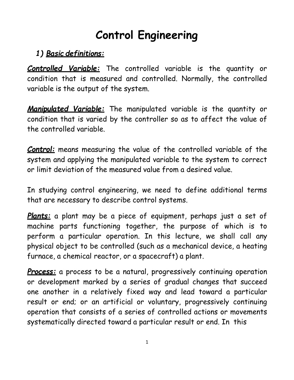
Control Engineering 1) Basicdefinitions: Controlled Variable: The controlled variable is the quantity or condition that is measured and controlled. Normally, the controlled variable is the output of the system. Manipulated Variable: The manipulated variable is the quantity or condition that is varied by the controller so as to affect the value of the controlled variable. Control: means measuring the value of the controlled variable of the system and applying the manipulated variable to the system to correct or limit deviation of the measured value from a desired value. In studying control engineering, we need to define additional terms that are necessary to describe control systems. Plants: a plant may be a piece of equipment, perhaps just a set of machine parts functioning together, the purpose of which is to perform a particular operation. In this lecture, we shall call any physical object to be controlled (such as a mechanical device, a heating furnace, a chemical reactor, or a spacecraft) a plant. Process: a process to be a natural, progressively continuing operation or development marked by a series of gradual changes that succeed one another in a relatively fixed way and lead toward a particular result or end; or an artificial or voluntary, progressively continuing operation that consists of a series of controlled actions or movements systematically directed toward a particular result or end. In this 1
lecture we shall call any operation to be controlled a process. Examples are chemical, economic, and biological processes. Systems: a system is a combination of components that act together and perform a certain objective. A system is not limited to physical ones. The concept of the system can be applied to abstract, dynamic phenomena such as those encountered in economics. The word system should, therefore, be interpreted to imply physical, biological, economic, and the like, systems. Disturbances: a disturbance is a signal that tends to adversely affect the value of the output of a system. If a disturbance is generated within the system, it is called internal, while an external disturbance is generated outside the system and is an input. Feedback Control: Feedback control refers to an operation that, in the presence of disturbances, tends to reduce the difference between the output of a system and some reference input and does so on the basis of this difference. Here only unpredictable disturbances are so specified, since predictable or known disturbances can always be compensated for within the system. 2) Examples of ControlSystems Here we shall present several examples of control systems: Speed Control System: The basic principle of a Watt's speed governor for an engine is illustrated in the schematic diagram of Figure 1-1.The amount of fuel admitted to the engine is adjusted according to the difference between the desired and the actual engine speeds. The sequence of actions may be stated as follows: The speed governor is adjusted such that, at the desired speed, no pressured oil will flow into either side of the power cylinder. If the actual speed drops below 2
the desired value due to disturbance, then the decrease in the centrifugal force of the speed governor causes the control valve to move downward, supplying more fuel, and the speed of the engine increases until the desired value is reached. On the other hand, if the speed of the engine increases above the desired value, then the increase in the centrifugal force of the governor causes the control valve to move upward. This decreases the supply of fuel, and the speed of the engine decreases until the desired value is reached. In this speed control system, the plant (controlled system) is the engine and the controlled variable is the speed of the engine. The difference between the desired speed and the actual speed is the error signal. The control signal (the amount of fuel) to be applied to the plant (engine) is the actuating signal. The external input to disturb the controlled variable is the disturbance. An unexpected change in the load is a disturbance. 3
Temperature Control System: Figure 1-2 shows a schematic diagram of temperature control of an electric furnace. The temperature in the electric furnace is measured by a thermometer, which is an analog device. The analog temperature is converted to a digital temperature by an A/D converter. The digital temperature is fed to a controller through an interface. This digital temperature is compared with the programmed input temperature, and if there is any discrepancy (error), the controller sends out a signal to the heater, through an interface, amplifier, and relay, to bring the furnace temperature to a desired value. 4

