Understanding Computer System Components and Software Types
Explore the essential components of a computer system, including hardware and software. Learn about the different types of software such as system software, development software, and application software. Delve into the functions of system software and examples of utility software. Discover the architecture of a typical microcomputer and the role of memory in computer systems.

Download Presentation

Please find below an Image/Link to download the presentation.
The content on the website is provided AS IS for your information and personal use only. It may not be sold, licensed, or shared on other websites without obtaining consent from the author. Download presentation by click this link. If you encounter any issues during the download, it is possible that the publisher has removed the file from their server.
E N D
Presentation Transcript
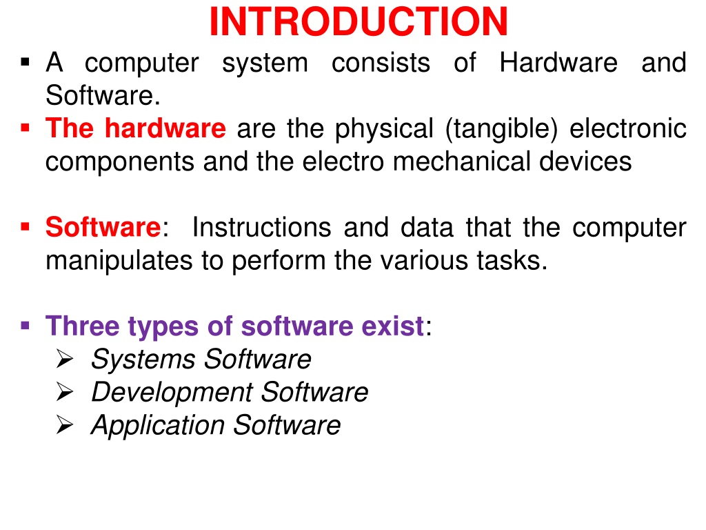
INTRODUCTION A computer system consists of Hardware and Software. The hardware are the physical (tangible) electronic components and the electro mechanical devices Software: Instructions and data that the computer manipulates to perform the various tasks. Three types of software exist: Systems Software Development Software Application Software
The system software Programs that control the operation of the machine and carry out the most basic functions the computer performs. o input data o produce output o manages and stores data o carries out or execute instructions of other programs etc.
Examples of system software Language processors Accept people like languages and translate them into machine language e.g. compilers, interpreters and assemblers Loaders They put the machine language program in memory and prepare it for execution Macro processors Allow programmers to use abbreviations
Examples of system software Utility software The software that is used for the other software to make their work proper, e.g. Anti viruses, Device drivers etc. Operating systems and file systems Allow flexible inputting, retrieval of information. outputting, storing and
Application Software Programs written by the user for purposes of solving particular problems using a computer as a tool e.g. application packages (word, Excel, PowerPoint etc). Development Software Programs used to create, update and maintain other programs e.g. programming languages. Systems software supports the operation and use of the computer itself rather than any particular application. They are therefore related to the structure of the machine on which they are to run.
MICRO COMPUTER ARCHITECTURE A typical Computer has 4 main functional parts: (i) The Microprocessor (CPU) (ii) Memory System (iii) Systems Interconnection System Bus Interfaces (Ports) (iv) I/O Sub System I/O Devices Mass Storage Devices
MICRO COMPUTER ARCHITECTURE Memory
MICRO COMPUTER ARCHITECTURE The microprocessor (CPU) Decodes instructions and use them to control all the activities within the system It also performs the Arithmetic (+ , -, /, *) and Logical (>,>=,<,<=,=,=!) computations. Memory Stores both data and instructions that are currently being used.
MICRO COMPUTER ARCHITECTURE System Interconnection Consists of : (i) System Bus: A set of conductors that connects the CPU to its memory and I/O devices. (ii) Interfaces Circuitry needed to connect the bus to a device.
MICRO COMPUTER ARCHITECTURE The I/O Sub System Consists of: (i) I/O devices For communicating with the external world. e.g keyboards, light pens etc for input and CRT monitors, printers, and plotters for output. (ii) Mass storage units For storing large quantities of information permanently. magnetic tapes, disk units, magnetic bubble memory etc
THE Microprocessor (CPU) It is made up of three main parts namely: The control unit Working registers The Arithmetic and Logic Unit
THE CPU (Cont.) The control Unit It consists of the following registers: The Program Counter (PC) Instruction Register (IR) Processor Status Word (PSW) Stack Pointer (SP) The Program Counter (PC) It holds the address of the main memory location from which the next instruction is to be fetched. Instruction Register (IR) Receives the instruction when it is brought from memory and holds it while it gets decoded and executed.
THE CPU (Cont.) Processor Status Word (PSW) contains condition flags which indicate the current status of the CPU and the important characteristics of the result of the previous instruction. Stack Pointer (SP): It hold the address on top of the stack.
THE CPU (Cont.) Working Registers Arithmetic Registers (Accumulators) Temporarily hold the operands and the result of the arithmetic operations. Address Registers For addressing data and instructions in main memory. If a register can be used for both arithmetic operations and addressing it is then called a general purpose register.
THE CPU (Cont.) Arithmetic/Logic Unit It performs arithmetic and logical operations on the contents of the working registers, the PC, memory locations etc. It also sets and clears the appropriate flags.
THE INTEL 8085 CPU (Cont.) It is an 8 bit processor i.e. has 8 data lines (1 byte of data can be transmitted at a time.) Has 6 general purpose registers namely B, C, D, E, H, L with 8 bits each and associated in pairs. (BC, DE, HL) 1 8 bit accumulator. 1 16 bit stack pointer 1 16 bit program counter
THE INTEL 8085 CPU (Cont.) 16 address and data lines (address space is 0 216 -1) The addresses and data share the same bus lines and they take turns to use them. (They are time multiplexed). The address must be sent first and then data is sent or received. 20 control lines i.e. it has 20 control signals.
THE INTEL 8085 CPU (Cont.) 1 PSW with 5 flags. Zero (Z): set when the result of the operation is zero. Sign (S): set when sign of the result is negative. Parity (P): When the parity of the bits in the result is even. Carry (C): Addition resulted into a carry or subtraction or comparison resulted into a borrow. Auxiliary Carry (AC)Carry in BCD arithmetic.
MACHINE LANGUAGE INSTRUCTIONS At the time of execution all instructions are made up of a sequence of zeros and ones which are understood by the computer. The language which is understood by the machine is therefore called machine language instruction. All other forms of programs (assembler, high level etc) must be reduced to their machine level form.
INSTRUCTION FORMATS Operation Code (Opcode). The portion of the instruction that specifies what the instruction does. Operand Any address or piece of data that is required by the instruction to complete its execution
INTEL 8085 EXAMPLES Register to Register Transfer 0 1 D D D S S S Opcode Destination Source
Register Codes Register Address B 000 C 001 D 010 E 011 H 100 L 101 A 111 Register pair BC 00 DE 01 HL 10 Both registers in the pair have the same higher 2 bits in their registers.
EXAMPLES Register to Register Transfer 0 1 0 0 0 1 1 1 Opcode Destination ( Register B) Source ( Register A ) The instruction copies contents of register A (111) to register B (000); register A remains with its contents.
EXAMPLES Add Contents of Register SSS to the Accumulator 1 0 0 0 0 S S S Opcode Source Register The instruction adds what is in a register described by the three bits SSS to contents of the accumulator; the answer stays in the accumulator.
Example Subtract contents of register SSS from the accumulator 1 0 0 1 0 S S S The instruction subtracts contents of the register whose address are the three bits SSS from the accumulator. The answer accumulator. stays in the
Example Transfer of Immediate Data to a Register Opcode Destination Register 0 0 D D D 0 1 0 The immediate data The instruction puts immediate data into the destination register DDD
Example Transfer of Immediate Data to a Register Opcode Destination Register 0 0 1 1 1 0 1 0 0 0 0 0 1 1 0 0 The data The instruction puts an integer 12 into register A (111)
Example Add Immediate data to Register A 1 1 0 0 0 1 1 0 Immediate Data The instruction adds the number in the second byte (data) to what is in the accumulator. The answer remains in the accumulator.
Example Subtract Immediate data from Register A 1 1 0 1 0 1 1 0 Immediate Data The instruction subtracts the number in the second byte (data) from what is in the accumulator. The answer remains in the accumulator.
Example Load Accumulator from memory Opcode 0 0 1 1 1 0 1 0 Lower part of the address Upper part of the address The instruction moves contents of a memory location whose address is specified in the two bytes to the accumulator. Operand (Address)
More Examples Store contents of the accumulator to memory Opcode 0 0 1 1 0 0 1 0 Lower part of the address Upper part of the address The instruction accumulator to a memory location whose address is specified in the given address. Operand (Address) stores contents of the
Example Conditional Branches Opcode Condition Code (if zero) 1 1 C C C 0 1 0 Lower part of the address Higher part of the address The instruction makes the program to branch to the given address if the given condition (C C C) is satisfied.
Condition Codes Conditions NZ Not Zero Z Zero NC No Carry C Carry PO Parity Odd PE Parity even P Plus M Minus CCC (z = 0) (z = 1) (c = 0) (c = 1) (p =0) (p =1) (s = 0) (s=1) 000 001 010 011 100 101 110 111
Example Branch if Zero Opcode Condition Code (if zero) 1 1 0 0 1 0 1 0 Lower part of the address Higher part of the address The instruction makes the program to branch to the given address if the given condition (001, if zero) is satisfied.
ADDRESSING MODES They are the methods used to locate and fetch an operand from an internal CPU register or from a memory location. Each processor has its own addressing modes. Immediate Addressing Information is part of the instruction. They are usually 2 byte instructions where the operand is the second byte. Direct addressing The address is part of the instruction.
ADDRESSING MODES Register addressing: The operand is in the register and the register s address is part of the instruction. Indirect Addressing: The address is in the location whose address is specified as part of the instruction. This location may be a register (register indirect addressing) or it may be a memory location.
ADDRESSING MODES Base addressing: The required address is calculated by adding the contents of a memory location or register called a base to a number called a displacement which is part of the instruction. Index Addressing It is a process of incrementing or decrementing an address as the computer sequences through a set of consecutive or evenly spaced addresses. This is done by successively changing an address that is stored in a register called an index register that can be incremented or decremented.
ASSEMBLER LANGUAGE It is a type of language that is closer to machine language instructions. There is an assembler language instruction for each machine language instruction. An assembler converts Assembler Language into machine instructions.
ASSEMBLER LANGUAGE There are 2 types of statements in assembler: (i) Instructions: These are translated into machine code by the assembler. (ii) Directive: Gives directions to the assembler during the assembly process but they are not translated into machine code. Acronyms called mnemonics indicate the type of instruction. Character strings called symbols or identifiers represent addresses and perhaps numbers.
EXAMPLE ANS: = X + Y using the Intel 8085 microprocessor. LDA X MOV B, A LDA Y ADD B STA ANS
Assembler Instruction Format Label: Mnemonic Operand, Operand, ; remarks Label: It is a symbol assigned to the address of the first byte of the instruction in which it appears. Its presence is optional. All instruction must contain a mnemonic. The presence of operands depends on the instruction. If there is more than one operand they are separated by a comma. Remarks are for documenting the program; they are optional.
EXAMPLES OF INTEL 8085 INSTRUCTIONS BRADDR: MOV A, M Label mnemonic destination Source Operand Operand Register Register Transfer e.g. NOW: MOV B, D Label mnemonic destination Source Operand Operand
EXAMPLES OF INTEL 8085 INSTRUCTIONS Transfer of Data from Memory LDA NUM Mnemonic address of operand in memory Transfer of immediate operand to a register e.g. MVI E, 6 Mnemonic Destination register Immediate Data
EXAMPLES OF INTEL 8085 INSTRUCTIONS Conditional branch on non-zero branch e.g. JNZ HERE Mnemonic Branch Condition address
DIRECTIVES They direct the assembler during the assembly process. They have the format Label: Mnemonic operand, Operand The label is optional
INTEL 8085 DIRECTIVES DS (Define Storage) It reserves memory and assigns a label to the first byte of the reserved area. e.g. ARRAY: DS 20 Reserves 20 bytes and assigns the label ARRAY to the byte with the lowest address.
INTEL 8085 DIRECTIVES DB (Define Byte) Used to put values into or pre-assign values to memory locations as well as reserve space and assign labels. e.g. NUM: DB reserves 5 bytes associated with a label NUM with the first byte. 14 41 42 43 68 14H, ABC ,01101000B Num
INTEL 8085 DIRECTIVES DW (Define Word) It reserves words instead of bytes. The lower order byte of the word is stored in the lower byte address and the high order byte in the higher byte address e.g. E.g. TABLE: Assuming that TASK1 and TASK2 have been assigned memory locations respectively DW TASK1, TASK2, 092AH 2010 and 108C Table 10 20 8C 10 2A 09


")

")
")
")
")

")
")
")