UBSUP
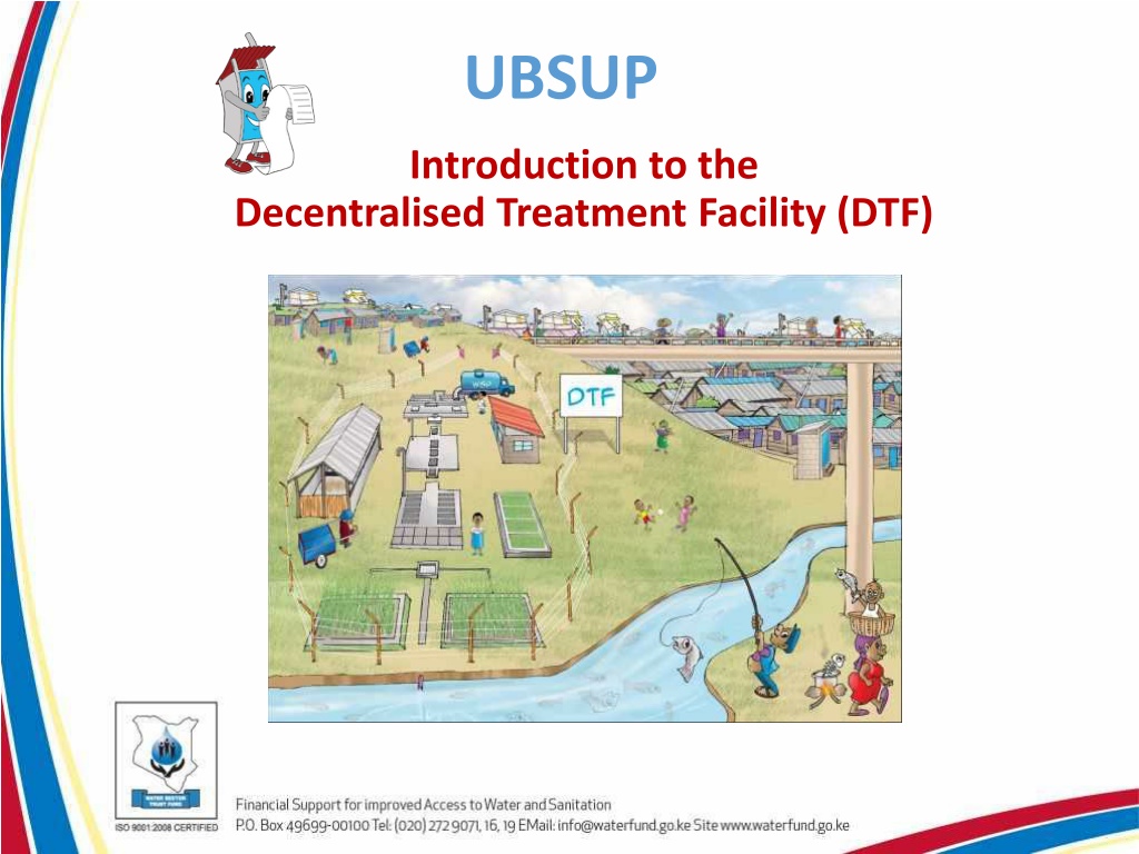

Introduction to the
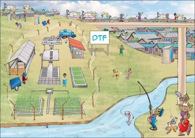
Decentralised Treatment Facility (DTF)
UBSUP

Low Income Area
Pit latrines
Septic tanks
UDDT
Sanigo
Exhauster
Exhauster
DTF
DTF
T
HE
C
ONCEPT
1.
Receiving Bay /
Balancing tank
(RBBT)
2.
Settler (ST)
3.
Anaerobic Baffled
Reactor (ABR)
4.
Vertical Flow
Constructed
Wetland (VFCW)
5.
Sludge Drying Reed
Beds (SDRB)
6.
Composting Area
(CA)
7.
Operator Store
(OS)
T
HE
DTF M
ODULES
T
HE
T
REATMENT
Mechanical and biological treatment
NO CHEMICALS !!
NO ELECTRICITY !!
DTF r
uns by gravity
I
N
D
ETAILS
1
Operator Store
•
Operator’s office
•
Entrance registration desk
•
Storage room for equipment
2
Receiving Bay / Balancing Tank
•
Screening of the coarse material
•
Storage of the effluent
•
Flow control to provide constant
inflow to the DTF
I
N
D
ETAILS
3
Settler
•
2 consecutive chambers separated
with a baffle wall
•
Sedimentation of settable solid
•
Flotation of fat and oil
4
Anaerobic Baffled Reactor
•
2 rows of 6 consecutive chambers with
down pipes
anaerobic treatment
through the settled sludge
•
1 siphon chamber
to release
intermittent flow
I
N
D
ETAILS
5
6
7
•
2 basins filled with successive gravel and sand
layers planted with aquatic plants
•
Perforated pipes on top (to feed) and at the
bottom (to receive)
•
FiItration, and aerobic treatment
Vertical Flow Constructed Wetland
Sludge Drying Beds
•
2 to 4 non planted beds filled with successive gravel
and sand layers
•
Filtration and evaporation
Composting Area
•
Composting shed
•
Mix dry sludge and organic waste to produce compost
Decentralised Treatment Facility (DTF) offers a sustainable solution for managing wastewater in low-income areas. The concept involves various modules such as Receiving Bay/Balancing Tank, Settler, Anaerobic Baffled Reactor, Vertical Flow Constructed Wetland, Sludge Drying Reed Beds, Composting Area, and Operator Store. The treatment process is chemical-free and operates without electricity, relying on mechanical and biological treatment run by gravity. Each module plays a crucial role in treating wastewater efficiently, from initial screening to compost production.

Download Presentation

Please find below an Image/Link to download the presentation.
The content on the website is provided AS IS for your information and personal use only. It may not be sold, licensed, or shared on other websites without obtaining consent from the author.If you encounter any issues during the download, it is possible that the publisher has removed the file from their server.
You are allowed to download the files provided on this website for personal or commercial use, subject to the condition that they are used lawfully. All files are the property of their respective owners.
The content on the website is provided AS IS for your information and personal use only. It may not be sold, licensed, or shared on other websites without obtaining consent from the author.
E N D
Presentation Transcript
UBSUP Introduction to the Decentralised Treatment Facility (DTF)
THE CONCEPT DTF Sanigo Exhauster Exhauster UDDT Pit latrines Septic tanks Low Income Area
THE DTF MODULES 1. Receiving Bay / Balancing tank (RBBT) 1 3 2. Settler (ST) 3. Anaerobic Baffled Reactor (ABR) 7 4. Vertical Flow Constructed Wetland (VFCW) 2 6 5. Sludge Drying Reed Beds (SDRB) 4 5 6. Composting Area (CA) 7. Operator Store (OS)
THE TREATMENT NO CHEMICALS !! Mechanical and biological treatment NO ELECTRICITY !! DTF runs by gravity
IN DETAILS Operator Store 1 Operator s office Entrance registration desk Storage room for equipment Receiving Bay / Balancing Tank 2 Screening of the coarse material Storage of the effluent Flow control to provide constant inflow to the DTF
IN DETAILS Settler 3 2 consecutive chambers separated with a baffle wall Sedimentation of settable solid Flotation of fat and oil Anaerobic Baffled Reactor 4 2 rows of 6 consecutive chambers with down pipes anaerobic treatment through the settled sludge 1 siphon chamber to release intermittent flow
IN DETAILS Vertical Flow Constructed Wetland 5 2 basins filled with successive gravel and sand layers planted with aquatic plants Perforated pipes on top (to feed) and at the bottom (to receive) FiItration, and aerobic treatment Sludge Drying Beds 6 2 to 4 non planted beds filled with successive gravel and sand layers Filtration and evaporation Composting Area 7 Composting shed Mix dry sludge and organic waste to produce compost