Thermocouple formation on PC Boards
Thermocouple formation on PC Boards
Content by Ian Williams and Thomas Kuehl
Precision Amplifiers Applications Engineering
Texas Instruments Incorporated - Tucson
1
T
h
e
r
m
o
c
o
u
p
l
e
T
h
e
o
r
y
2
+
-
H
o
t
C
o
o
l
Temperature gradient (
∆T)
C
o
n
d
u
c
t
o
r
T
H
T
C
•
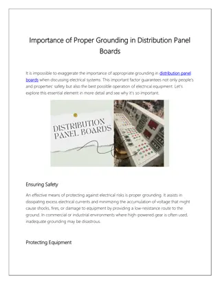
Any conductor will produce a voltage when there is a temperature
gradient (
Δ
T) across it
–
K
n
o
w
n
a
s
t
h
e
“
S
e
e
b
e
c
k
E
f
f
e
c
t
”
Seebeck voltage
E
l
e
c
t
r
i
c
a
l
c
h
a
r
g
e
c
a
r
r
i
e
r
m
o
v
e
m
e
n
t
T
h
e
r
m
a
l
e
n
e
r
g
y
f
l
o
w
T
h
e
r
m
o
c
o
u
p
l
e
T
h
e
o
r
y
3
Source: www.efunda.com
T
h
e
r
m
o
c
o
u
p
l
e
T
h
e
o
r
y
4
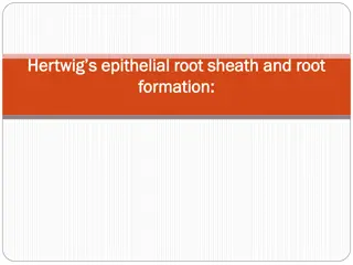
Positive Seebeck
coefficient
Negative
Seebeck
coefficient
Temperature
measurement
junction
+
–
Constantan
Copper
T
h
e
r
m
a
l
e
n
e
r
g
y
f
l
o
w
6
.
5
u
V
/
°
C
-
3
5
u
V
/
°
C
E
l
e
c
t
r
i
c
a
l
c
h
a
r
g
e
c
a
r
r
i
e
r
m
o
v
e
m
e
n
t
E
l
e
c
t
r
i
c
a
l
c
h
a
r
g
e
c
a
r
r
i
e
r
m
o
v
e
m
e
n
t
4
1
.
5
u
V
/
°
C
•
D
i
f
f
e
r
e
n
t
m
e
t
a
l
s
h
a
v
e
d
i
f
f
e
r
e
n
t
t
h
e
r
m
a
l
s
e
n
s
i
t
i
v
i
t
i
e
s
•
Two metals can be joined together to create a practical temperature
measurement device with a known thermoelectric behavior
•
Junctions of dissimilar conductors are everywhere on a PCB!
–
Components soldered to a copper pad
–
Wires mechanically attached to the PCB
–
Jumpers and connectors
–
Solder joints
–
PCB vias
T
h
e
r
m
o
c
o
u
p
l
e
s
o
n
P
C
B
s
5
Source: “Op Amp Precision Design: PCB Layout Techniques”
T
h
e
r
m
o
c
o
u
p
l
e
s
o
n
P
C
B
s
6
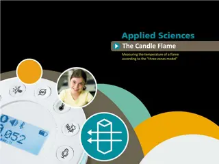
•
If temperature gradients are present, these junctions will create a
thermoelectric voltage.
•
In
this example, a temperature gradient of +1.2
°
C caused a total of
-38 µV to appear across a resistor.
Source: “Op Amp Precision Design: PCB Layout Techniques”
T
e
s
t
C
a
s
e
:
I
N
A
3
3
3
V
O
S
C
i
r
c
u
i
t
–
n
o
n
-
s
y
m
m
e
t
r
i
c
a
l
T
e
s
t
i
n
g
v
i
a
s
a
n
d
0
Ω
r
e
s
i
s
t
o
r
s
f
o
r
t
h
e
r
m
o
c
o
u
p
l
e
b
e
h
a
v
i
o
r
7
INA333
Av = 101 V/V
I
N
A
3
3
3
V
O
S
C
i
r
c
u
i
t
(
S
y
m
m
e
t
r
i
c
a
l
)
T
e
s
t
i
n
g
v
i
a
s
a
n
d
0
Ω
r
e
s
i
s
t
o
r
s
f
o
r
t
h
e
r
m
o
c
o
u
p
l
e
b
e
h
a
v
i
o
r
8
INA333
Av = 101 V/V
I
N
A
3
3
3
V
O
S
C
i
r
c
u
i
t
L
a
y
o
u
t
9
I
N
A
3
3
3
V
O
S
R
e
s
u
l
t
s
–
0
Ω
R
e
s
i
s
t
o
r
s
10
I
N
A
3
3
3
V
O
S
R
e
s
u
l
t
s
–
V
i
a
s
11
2
4
µ
V
1
6
µ
V
T
h
e
r
m
o
c
o
u
p
l
e
s
-
C
o
n
c
l
u
s
i
o
n
s
12
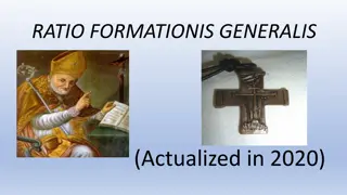
•
Parasitic thermocouples can have a significant impact on V
OS
!
•
As expected, asymmetrical configurations see a much more
pronounced increase in offset voltage
•
0
Ω
resistors key result -
V
OS
(RTI) increased by up to 17µV!
•
Vias key result - V
OS
(RTI) increased by up to 250nV
–
Difference small enough to be solely caused by INA V
OS
and gain drift
•
Additional testing will be done to isolate the thermocouple effect from
the V
OS
and gain error drift of the INA333
T
h
e
r
m
o
c
o
u
p
l
e
s
-
R
e
c
o
m
m
e
n
d
a
t
i
o
n
s
13
•
Use symmetrical configurations to minimize V
OS
and CMRR
degradation
•
Isolate sensitive nodes from thermal gradients by removing copper
pours which dissipate heat
•
Reduce the board’s heat generation or redirect the heat flow away from
critical areas through the use of heat sinks or fans
•
Place critical components in areas of constant temperature
–
Heat travels radially, so follow thermal contour lines
•
Use materials with similar Seebeck coefficients (when possible)
•
Replace single resistors with equivalent parallel resistor combinations
in order to cancel thermoelectric voltages
T
h
e
r
m
o
c
o
u
p
l
e
s
-
R
e
c
o
m
m
e
n
d
a
t
i
o
n
s
14
Components aligned with
thermal contour lines
Series resistor substitution
Source: “Op Amp Precision Design: PCB Layout Techniques”
Thermocouples play a crucial role in measuring temperature gradients on PCBs. Learn about the Seebeck effect, thermocouple theory, junctions of dissimilar conductors, and testing techniques using precision amplifiers. Understand how temperature gradients create thermoelectric voltages and the practical applications of thermocouples on PCBs.

Download Presentation

Please find below an Image/Link to download the presentation.
The content on the website is provided AS IS for your information and personal use only. It may not be sold, licensed, or shared on other websites without obtaining consent from the author.If you encounter any issues during the download, it is possible that the publisher has removed the file from their server.
You are allowed to download the files provided on this website for personal or commercial use, subject to the condition that they are used lawfully. All files are the property of their respective owners.
The content on the website is provided AS IS for your information and personal use only. It may not be sold, licensed, or shared on other websites without obtaining consent from the author.
E N D
Presentation Transcript
Thermocouple formation on PC Boards Content by Ian Williams and Thomas Kuehl Precision Amplifiers Applications Engineering Texas Instruments Incorporated - Tucson 1
Thermocouple Theory Seebeck voltage + - Conductor Thermal energy flow Cool Hot Electrical charge carrier movement TC TH Temperature gradient ( T) Any conductor will produce a voltage when there is a temperature gradient ( T) across it Known as the Seebeck Effect 2
Thermocouple Theory Source: www.efunda.com 3
Thermocouple Theory Positive Seebeck coefficient Temperature measurement junction Electrical charge carrier movement + Copper 6.5uV/ C Thermal energy flow 41.5uV/ C Constantan -35uV/ C Electrical charge carrier movement NegativeSeebeck coefficient Different metals have different thermal sensitivities Two metals can be joined together to create a practical temperature measurement device with a known thermoelectric behavior 4
Thermocouples on PCBs Junctions of dissimilar conductors are everywhere on a PCB! Components soldered to a copper pad Wires mechanically attached to the PCB Jumpers and connectors Solder joints PCB vias Resistor film Copper traces Resistor end caps Junction #1 Junction #2 Junction #4 Junction #3 Source: Op Amp Precision Design: PCB Layout Techniques 5
Thermocouples on PCBs If temperature gradients are present, these junctions will create a thermoelectric voltage. 8.999 mV 14.010 mV 14.000 mV 0 mV -0.038 mV 125.0 C 125.1 C 126.2 C 126.1 C In this example, a temperature gradient of +1.2 C caused a total of -38 V to appear across a resistor. Source: Op Amp Precision Design: PCB Layout Techniques 6
Test Case: INA333 VOS Circuit non-symmetrical Testing vias and 0 resistors for thermocouple behavior INA333 Av = 101 V/V GND R1 -2.5V R3 R4 R5 R6 R7 1.00Meg C3 0 0 0 0 0 R13 0.1 F 3 0 2 2 7 - U1 INA333 1 GND V- R15 1 RG J1 U1 OUT 0 R17 6 1 TP1 TP2 TP3 TP4 TP5 Out 1.00k R19 8 Ref 5 4 3 2 RG R21 3 0 V+ 10.0k 2 3 142-0701-201 + 5 1 4 R23 C1 J5 0 GND 0.1 F GND VRef 2.5V GND R30 1.00Meg GND 7
INA333 VOS Circuit (Symmetrical) Testing vias and 0 resistors for thermocouple behavior INA333 Av = 101 V/V GND R2 R8 R9 R10 R11 R12 1.00Meg -2.5V 0 0 0 0 0 C4 R14 3 0 0.1 F 2 2 7 - U2 INA333 1 V- R16 1 GND RG J3 U2 OUT 0 R18 6 1 TP6 TP7 TP8 TP9 TP10 Out 1.00k R20 8 Ref 5 4 3 2 RG R22 3 0 V+ 10.0k 2 3 142-0701-201 + 5 TP11 TP12 TP13 TP14 TP15 1 4 R24 J6 GND C2 0 R25 R26 R27 R28 R29 GND 0.1 F 0 0 0 0 0 GND VRef 2.5V R31 1.00Meg GND 8
INA333 VOS Results 0 Resistors 0 Ohm Resistors, Output Voltage Averaged Over 10 Minutes 2000 1698 V 1800 1600 Output Voltage Magnitude (uV) 1400 1200 1000 800 600 400 177 V 200 0 Asymmetrical Symmetrical Cold Hot 10
INA333 VOS Results Vias Vias, Output Voltage Averaged Over 10 Minutes 120 24 V 100 Output Voltage Magnitude (uV) 80 60 40 16 V 20 0 Asymmetrical Symmetrical Cold Hot 11
Thermocouples - Conclusions Parasitic thermocouples can have a significant impact on VOS! As expected, asymmetrical configurations see a much more pronounced increase in offset voltage 0 resistors key result - VOS (RTI) increased by up to 17 V! Vias key result - VOS (RTI) increased by up to 250nV Difference small enough to be solely caused by INA VOS and gain drift Additional testing will be done to isolate the thermocouple effect from the VOS and gain error drift of the INA333 12
Thermocouples - Recommendations Use symmetrical configurations to minimize VOS and CMRR degradation Isolate sensitive nodes from thermal gradients by removing copper pours which dissipate heat Reduce the board s heat generation or redirect the heat flow away from critical areas through the use of heat sinks or fans Place critical components in areas of constant temperature Heat travels radially, so follow thermal contour lines Use materials with similar Seebeck coefficients (when possible) Replace single resistors with equivalent parallel resistor combinations in order to cancel thermoelectric voltages 13
Thermocouples - Recommendations Components aligned with thermal contour lines Series resistor substitution Source: Op Amp Precision Design: PCB Layout Techniques 14


")