Stratus: Mobile Device Storage and Management System Overview
Stratus is a mobile device storage solution accessed via Wi-Fi, utilizing a micro SD card for data storage and featuring a graphical display. Powered by a lithium polymer battery, Stratus allows streaming of information, battery system management, SD card data read/write, file selection via a mobile app, and display of essential information to users. The project includes detailed specifics on component selection, block diagram, and Wi-Fi module rationale.
Download Presentation

Please find below an Image/Link to download the presentation.
The content on the website is provided AS IS for your information and personal use only. It may not be sold, licensed, or shared on other websites without obtaining consent from the author.If you encounter any issues during the download, it is possible that the publisher has removed the file from their server.
You are allowed to download the files provided on this website for personal or commercial use, subject to the condition that they are used lawfully. All files are the property of their respective owners.
The content on the website is provided AS IS for your information and personal use only. It may not be sold, licensed, or shared on other websites without obtaining consent from the author.
E N D
Presentation Transcript
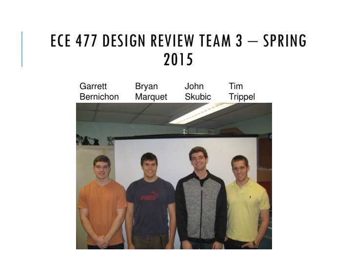
ECE 477 DESIGN REVIEW TEAM 3 SPRING 2015 Garrett Bernichon Bryan Marquet John Skubic Tim Trippel
OUTLINE Project overview Project-specific success criteria Block diagram Component selection rationale Schematic and theory of operation PCB layout Packaging design Software design/development status Project completion timeline Questions / discussion
PROJECT OVERVIEW Stratus provides additional storage for mobile devices The storage is accessed from a Wi-Fi hotspot Data is stored on Stratus via a micro SD card System status is presented via a graphical display Stratus is powered by a lithium polymer battery chargeable by a USB cable
PROJECT-SPECIFIC SUCCESS CRITERIA An ability to stream information from Stratus to an external device using Wi-Fi. An ability to charge and manage a battery system, and inform the microcontroller of remaining charge. An ability to read and write data to a SD card unit connected to Stratus. An ability to browse and select files to stream from Stratus via a mobile app. An ability to display information such as battery life, Wi-Fi connection status, and name of current file being accessed to the user via a graphics display connected to Stratus.
COMPONENT SELECTION RATIONALE: MICROCONTROLLER Texas Instruments TM4C123GH6PM Atmel ATSAME70J19 (SAM E Series) (Tiva C Series) 32-bit ARM Cortex M4 32-bit ARM Cortex M7 80 MHz max system clock 300 MHz max system clock 4 SPI channels 3 SPI channels 32 DMA channels 24 DMA channels 256 KB flash, 32 KB SRAM 512 KB flash, 256 KB SRAM
COMPONENT SELECTION RATIONALE: WI-FI VS. BLUETOOTH Wi-Fi + Higher throughput + More open - Power Consumption - Extra software for configuration as both an access-point or not Bluetooth + Low-power - Low throughput
COMPONENT SELECTION RATIONALE: WI-FI MODULE TI CC3100 + Creates a Wi-Fi hotspot - Module has pins on bottom TI CC3000 + small module with antenna - Can t create a Wi-Fi hotspot TI CC3200 + Has built-in ARM processor + Creates Wi-Fi hotpot - Requires an OS - Not hand solderable
COMPONENT SELECTION RATIONALE: DISPLAY Sharp LS013B4DN04 LCD E-Paper hybrid 1.35 screen + Low power consumption + No external circuit needed - More complex software RePaper E-Paper display 1.3 screen + Low power consumption + Simple software interface - Requires large external circuit - Requires 3.3V and 5.0V
COMPONENT SELECTION RATIONALE: BATTERY Constraints: Maximum size, must fit inside packaging Minimum capacity, aiming for six hours of heavy usage (heavy = 370 mA approx.) Decision: Polymer Lithium Ion Battery 2000 mAh
SCHEMATIC/THEORY OF OPERATION : MICROCONTROLLER Microcontroller System Clock Internal PLL to achieve 40 MHz 16 MHz External (for boot-up) Serial connections Battery Monitor (I2C) SD Card (SPI) Wi-Fi module (SPI) LCD (SPI)
SCHEMATIC/THEORY OF OPERATION : WI-FI Wi-Fi Module External module 20 MHz max SPI CLK Designing our own module Solderablility Antenna design
SCHEMATIC/THEORY OF OPERATION : LCD LCD/E-paper Hybrid Screen Interfaces with SPI at 1Mbps Setup so VCOM signal is set using SPI
SCHEMATIC/THEORY OF OPERATION : SD CARD SD Card Interfaces with SPI at ~20-25 Mbps Pull-Up resistors for idle (Hi-Z) lines SD requires idle to be high Power MOSFET for software control of hard-reset Chip-Detect signal
SCHEMATIC/THEORY OF OPERATION: POWER Power Management 5V USB charging 3.7V battery 3.3 V data bus
PCB LAYOUT Top: Bottom:
PCB LAYOUT Microcontroller: Battery:
PACKAGING DESIGN Dimensions: 90 x 57 x 13 (mm) Two 3D printed plastic pieces will be screwed together, one top and one bottom with sides Insulation will be added inside to aid in securing components. Battery Dimensions: 5.8 x 54 x 60 (mm) PCB Dimensions: 86 x 28 (mm)
SOFTWARE DEVELOPMENT STATUS Embedded Embedded Initializations System Status Interrupts Wi-Fi Interface DMA Controller Interrupts Main Control Loop iOS Development Using Python TCP server to act as Stratus Can request and receive music library Can request, receive, and play a song User Interface is 75% complete
PROJECT COMPLETION TIMELINE Week 8: Week 9: finalize board finish embedded initializations, finish iOS application, design own Wi-Fi module, battery communication spring break solder PCB components, Wi-Fi module interface, optimize file access (DMA) integrate all software components 3D print packaging, continue integration & testing continue integration & testing testing showcase week Week 10: Week 11: Week 12: Week 13: Week 14: Week 15: Week 16:


