SPICA-VIS Photometry Transport System Overview
This detailed overview outlines the intricate components of the SPICA-VIS photometry transport system, including modules for photometry, interferometry, dispersion, signal detection, and more. Key elements such as the optical fiber feeding optics, polarization delay compensator, atmospheric dispersion compensator, and image alignment devices are highlighted. The system's functionality, alignment mechanisms, and beam control systems are thoroughly discussed, offering a comprehensive look at the design and requirements of the SPICA-VIS setup.
Download Presentation

Please find below an Image/Link to download the presentation.
The content on the website is provided AS IS for your information and personal use only. It may not be sold, licensed, or shared on other websites without obtaining consent from the author.If you encounter any issues during the download, it is possible that the publisher has removed the file from their server.
You are allowed to download the files provided on this website for personal or commercial use, subject to the condition that they are used lawfully. All files are the property of their respective owners.
The content on the website is provided AS IS for your information and personal use only. It may not be sold, licensed, or shared on other websites without obtaining consent from the author.
E N D
Presentation Transcript
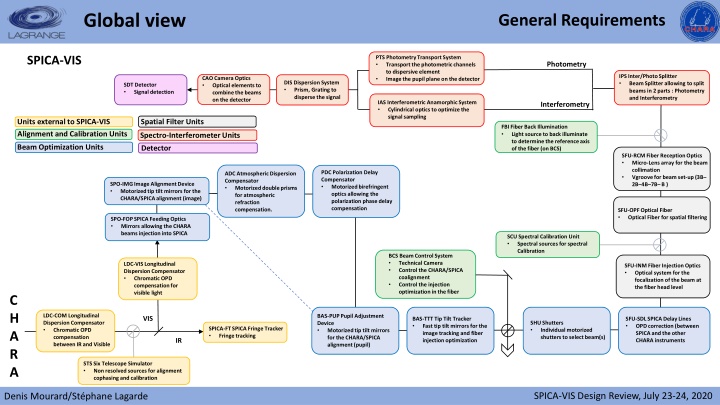
Global view General Requirements SPICA-VIS PTS Photometry Transport System Transport the photometric channels to dispersive element Image the pupil plane on the detector Photometry IPS Inter/Photo Splitter Beam Splitter allowing to split beams in 2 parts : Photometry and Interferometry CAO Camera Optics Optical elements to combine the beams on the detector DIS Dispersion System Prism, Grating to disperse the signal SDT Detector Signal detection IAS Interferometric Anamorphic System Cylindrical optics to optimize the signal sampling Interferometry Spatial Filter Units Units external to SPICA-VIS FBI Fiber Back Illumination Light source to back illuminate to determine the reference axis of the fiber (on BCS) Alignment and Calibration Units Spectro-Interferometer Units Beam Optimization Units Detector SFU-RCM Fiber Reception Optics Micro-Lens array for the beam collimation Vgroovefor beam set-up (3B 2B 4B 7B B ) PDC Polarization Delay Compensator Motorized birefringent optics allowing the polarization phase delay compensation ADC Atmospheric Dispersion Compensator Motorized double prisms for atmospheric refraction compensation. SPO-IMG Image Alignment Device Motorized tip tilt mirrors for the CHARA/SPICA alignment (image) SFU-OPF Optical Fiber Optical Fiber for spatial filtering SPO-FOP SPICA Feeding Optics Mirrors allowing the CHARA beams injection into SPICA SCU Spectral Calibration Unit Spectral sources for spectral Calibration BCS Beam Control System Technical Camera Control the CHARA/SPICA coalignment Control the injection optimization in the fiber LDC-VIS Longitudinal Dispersion Compensator Chromatic OPD compensation for visible light SFU-INM Fiber Injection Optics Optical system for the focalization of the beam at the fiber head level C H A R A LDC-COM Longitudinal Dispersion Compensator Chromatic OPD compensation between IR and Visible BAS-PUP Pupil Adjustment Device Motorized tip tilt mirrors for the CHARA/SPICA alignment (pupil) VIS BAS-TTT Tip Tilt Tracker Fast tip tilt mirrors for the image tracking and fiber injection optimization SFU-SDL SPICA Delay Lines OPD correction (between SPICA and the other CHARA instruments SHU Shutters Individual motorized shutters to select beam(s) SPICA-FT SPICA Fringe Tracker Fringe tracking IR STS Six Telescope Simulator Non resolved sources for alignment cophasing and calibration SPICA-VIS Design Review, July 23-24, 2020 Denis Mourard/St phane Lagarde
Modules before the optical fibers General Requirements Feeding Optics (SFO-FPO) Removable mirrors (motorized) Spec. Repeatability: <10as & <1mm PDC Polarization Delay Compensator Motorized birefringent optics allowing the polarization phase delay compensation ADC Atmospheric Dispersion Compensator Motorized double prisms for atmospheric refraction compensation. SPO-IMG Image Alignment Device Motorized tip tilt mirrors for the CHARA/SPICA alignment (image) SPO-FOP SPICA Feeding Optics Mirrors allowing the CHARA beams injection into SPICA BCS Beam Control System Technical Camera Control the CHARA/SPICA coalignment Control the injection optimization in the fiber BAS-PUP Pupil Adjustment Device Motorized tip tilt mirrors for the CHARA/SPICA alignment (pupil) BAS-TTT Tip Tilt Tracker Fast tip tilt mirrors for the image tracking and fiber injection optimization SFU-SDL SPICA Delay Lines OPD correction (between SPICA and the other CHARA instruments SHU Shutters Individual motorized shutters to select beam(s) SPICA-VIS Design Review, July 23-24, 2020 Denis Mourard/St phane Lagarde
Modules before the optical fibers General Requirements Low frequency beam adjustment (SPO-IMG & BAS-PUP) Slow tip/tilt mirrors (motorized) Spec. Accuracy: <10as & <1mm PDC Polarization Delay Compensator Motorized birefringent optics allowing the polarization phase delay compensation ADC Atmospheric Dispersion Compensator Motorized double prisms for atmospheric refraction compensation. SPO-IMG Image Alignment Device Motorized tip tilt mirrors for the CHARA/SPICA alignment (image) SPO-FOP SPICA Feeding Optics Mirrors allowing the CHARA beams injection into SPICA BCS Beam Control System Technical Camera Control the CHARA/SPICA coalignment Control the injection optimization in the fiber BAS-PUP Pupil Adjustment Device Motorized tip tilt mirrors for the CHARA/SPICA alignment (pupil) BAS-TTT Tip Tilt Tracker Fast tip tilt mirrors for the image tracking and fiber injection optimization SFU-SDL SPICA Delay Lines OPD correction (between SPICA and the other CHARA instruments SHU Shutters Individual motorized shutters to select beam(s) SPICA-VIS Design Review, July 23-24, 2020 Denis Mourard/St phane Lagarde
Modules before the optical fibers General Requirements Fast frequency beam adjustment (SPO-IMG & BAS-PUP) Fast tip/tilt mirrors (motorized) Spec. Accuracy: <1as Frequency: 200 Hz PDC Polarization Delay Compensator Motorized birefringent optics allowing the polarization phase delay compensation ADC Atmospheric Dispersion Compensator Motorized double prisms for atmospheric refraction compensation. SPO-IMG Image Alignment Device Motorized tip tilt mirrors for the CHARA/SPICA alignment (image) SPO-FOP SPICA Feeding Optics Mirrors allowing the CHARA beams injection into SPICA BCS Beam Control System Technical Camera Control the CHARA/SPICA coalignment Control the injection optimization in the fiber BAS-PUP Pupil Adjustment Device Motorized tip tilt mirrors for the CHARA/SPICA alignment (pupil) BAS-TTT Tip Tilt Tracker Fast tip tilt mirrors for the image tracking and fiber injection optimization SFU-SDL SPICA Delay Lines OPD correction (between SPICA and the other CHARA instruments SHU Shutters Individual motorized shutters to select beam(s) SPICA-VIS Design Review, July 23-24, 2020 Denis Mourard/St phane Lagarde
Modules before the optical fibers General Requirements Beam Control System (BCS) Visible camera for beam control Possibility to switch between image and pupil plans PDC Polarization Delay Compensator Motorized birefringent optics allowing the polarization phase delay compensation ADC Atmospheric Dispersion Compensator Motorized double prisms for atmospheric refraction compensation. SPO-IMG Image Alignment Device Motorized tip tilt mirrors for the CHARA/SPICA alignment (image) SPO-FOP SPICA Feeding Optics Mirrors allowing the CHARA beams injection into SPICA BCS Beam Control System Technical Camera Control the CHARA/SPICA coalignment Control the injection optimization in the fiber BAS-PUP Pupil Adjustment Device Motorized tip tilt mirrors for the CHARA/SPICA alignment (pupil) BAS-TTT Tip Tilt Tracker Fast tip tilt mirrors for the image tracking and fiber injection optimization SFU-SDL SPICA Delay Lines OPD correction (between SPICA and the other CHARA instruments SHU Shutters Individual motorized shutters to select beam(s) SPICA-VIS Design Review, July 23-24, 2020 Denis Mourard/St phane Lagarde
Modules before the optical fibers General Requirements Atmospheric Dispersion Correction (ADC) Prisms (2 per beam, motorized) Spec. Frequency: Every 10mns Accuracy: 0.5 PDC Polarization Delay Compensator Motorized birefringent optics allowing the polarization phase delay compensation ADC Atmospheric Dispersion Compensator Motorized double prisms for atmospheric refraction compensation. SPO-IMG Image Alignment Device Motorized tip tilt mirrors for the CHARA/SPICA alignment (image) SPO-FOP SPICA Feeding Optics Mirrors allowing the CHARA beams injection into SPICA BCS Beam Control System Technical Camera Control the CHARA/SPICA coalignment Control the injection optimization in the fiber BAS-PUP Pupil Adjustment Device Motorized tip tilt mirrors for the CHARA/SPICA alignment (pupil) BAS-TTT Tip Tilt Tracker Fast tip tilt mirrors for the image tracking and fiber injection optimization SFU-SDL SPICA Delay Lines OPD correction (between SPICA and the other CHARA instruments SHU Shutters Individual motorized shutters to select beam(s) SPICA-VIS Design Review, July 23-24, 2020 Denis Mourard/St phane Lagarde
Modules before the optical fibers General Requirements Polarization Delay Compensation (PDC) Birefringent plates (motorized) Spec. Accuracy: 0.1 PDC Polarization Delay Compensator Motorized birefringent optics allowing the polarization phase delay compensation ADC Atmospheric Dispersion Compensator Motorized double prisms for atmospheric refraction compensation. SPO-IMG Image Alignment Device Motorized tip tilt mirrors for the CHARA/SPICA alignment (image) SPO-FOP SPICA Feeding Optics Mirrors allowing the CHARA beams injection into SPICA BCS Beam Control System Technical Camera Control the CHARA/SPICA coalignment Control the injection optimization in the fiber BAS-PUP Pupil Adjustment Device Motorized tip tilt mirrors for the CHARA/SPICA alignment (pupil) BAS-TTT Tip Tilt Tracker Fast tip tilt mirrors for the image tracking and fiber injection optimization SFU-SDL SPICA Delay Lines OPD correction (between SPICA and the other CHARA instruments SHU Shutters Individual motorized shutters to select beam(s) SPICA-VIS Design Review, July 23-24, 2020 Denis Mourard/St phane Lagarde
Modules before the optical fibers General Requirements Shutters (SHU) Slow shutters (motorized) PDC Polarization Delay Compensator Motorized birefringent optics allowing the polarization phase delay compensation ADC Atmospheric Dispersion Compensator Motorized double prisms for atmospheric refraction compensation. SPO-IMG Image Alignment Device Motorized tip tilt mirrors for the CHARA/SPICA alignment (image) SPO-FOP SPICA Feeding Optics Mirrors allowing the CHARA beams injection into SPICA BCS Beam Control System Technical Camera Control the CHARA/SPICA coalignment Control the injection optimization in the fiber BAS-PUP Pupil Adjustment Device Motorized tip tilt mirrors for the CHARA/SPICA alignment (pupil) BAS-TTT Tip Tilt Tracker Fast tip tilt mirrors for the image tracking and fiber injection optimization SFU-SDL SPICA Delay Lines OPD correction (between SPICA and the other CHARA instruments SHU Shutters Individual motorized shutters to select beam(s) SPICA-VIS Design Review, July 23-24, 2020 Denis Mourard/St phane Lagarde
Modules before the optical fibers General Requirements Internal Delay Lines (SFU-SDL) Translation stages (motorized) Spec. Accuracy: <7 m PDC Polarization Delay Compensator Motorized birefringent optics allowing the polarization phase delay compensation ADC Atmospheric Dispersion Compensator Motorized double prisms for atmospheric refraction compensation. SPO-IMG Image Alignment Device Motorized tip tilt mirrors for the CHARA/SPICA alignment (image) SPO-FOP SPICA Feeding Optics Mirrors allowing the CHARA beams injection into SPICA BCS Beam Control System Technical Camera Control the CHARA/SPICA coalignment Control the injection optimization in the fiber BAS-PUP Pupil Adjustment Device Motorized tip tilt mirrors for the CHARA/SPICA alignment (pupil) BAS-TTT Tip Tilt Tracker Fast tip tilt mirrors for the image tracking and fiber injection optimization SFU-SDL SPICA Delay Lines OPD correction (between SPICA and the other CHARA instruments SHU Shutters Individual motorized shutters to select beam(s) SPICA-VIS Design Review, July 23-24, 2020 Denis Mourard/St phane Lagarde
Spatial Filters Modules General Requirements Fiber Injection Optics (SFU-INM) Lenses Spec. Injection Level: >70% (CHARA beam) FBI Fiber Back Illumination Light source to back illuminate to determine the reference axis of the fiber (on BCS) SFU-RCM Fiber Reception Optics Micro-Lens array for the beam collimation Vgroovefor beam set-up (3B 2B 4B 7B B ) SFU-OPF Optical Fiber Optical Fiber for spatial filtering SCU Spectral Calibration Unit Spectral sources for spectral Calibration SFU-INM Fiber Injection Optics Optical system for the focalization of the beam at the fiber head level SPICA-VIS Design Review, July 23-24, 2020
Spatial Filters Modules General Requirements Optical Fibers (SFU-OPF) Optical Fiber Spec. Equalization in dispersion: 0.2mm FBI Fiber Back Illumination Light source to back illuminate to determine the reference axis of the fiber (on BCS) SFU-RCM Fiber Reception Optics Micro-Lens array for the beam collimation Vgroovefor beam set-up (3B 2B 4B 7B B ) SFU-OPF Optical Fiber Optical Fiber for spatial filtering SCU Spectral Calibration Unit Spectral sources for spectral Calibration SFU-INM Fiber Injection Optics Optical system for the focalization of the beam at the fiber head level SPICA-VIS Design Review, July 23-24, 2020
Spatial Filters Modules General Requirements Fiber Reception Optics (SFU-RCM) Vgroove + Micro-Lens Array Spec. Beam Spacing: 3B-2B-4B-7B-B FBI Fiber Back Illumination Light source to back illuminate to determine the reference axis of the fiber (on BCS) SFU-RCM Fiber Reception Optics Micro-Lens array for the beam collimation Vgroovefor beam set-up (3B 2B 4B 7B B ) SFU-OPF Optical Fiber Optical Fiber for spatial filtering SCU Spectral Calibration Unit Spectral sources for spectral Calibration SFU-INM Fiber Injection Optics Optical system for the focalization of the beam at the fiber head level SPICA-VIS Design Review, July 23-24, 2020
Spatial Filters Modules General Requirements Spectral Calibration Unit (SCU) Spectral Lamp Spec. Calibration lines spacing: <25nm between 2 lines FBI Fiber Back Illumination Light source to back illuminate to determine the reference axis of the fiber (on BCS) SFU-RCM Fiber Reception Optics Micro-Lens array for the beam collimation Vgroovefor beam set-up (3B 2B 4B 7B B ) SFU-OPF Optical Fiber Optical Fiber for spatial filtering SCU Spectral Calibration Unit Spectral sources for spectral Calibration SFU-INM Fiber Injection Optics Optical system for the focalization of the beam at the fiber head level SPICA-VIS Design Review, July 23-24, 2020
Spatial Filters Modules General Requirements Fiber Back Illumination (FBI) White or laser source (motorized) Spec. Simultaneous Illumination of the 6 fibers FBI Fiber Back Illumination Light source to back illuminate to determine the reference axis of the fiber (on BCS) SFU-RCM Fiber Reception Optics Micro-Lens array for the beam collimation Vgroovefor beam set-up (3B 2B 4B 7B B ) SFU-OPF Optical Fiber Optical Fiber for spatial filtering SCU Spectral Calibration Unit Spectral sources for spectral Calibration SFU-INM Fiber Injection Optics Optical system for the focalization of the beam at the fiber head level SPICA-VIS Design Review, July 23-24, 2020
Modules of the Spectrograph General Requirements PTS Photometry Transport System Transport the photometric channels to dispersive element Image the pupil plane on the detector Photometry IPS Inter/Photo Splitter Beam Splitter allowing to split beams in 2 parts : Photometry and Interferometry CAO Camera Optics Optical elements to combine the beams on the detector DIS Dispersion System Prism, Grating to disperse the signal SDT Detector Signal detection IAS Interferometric Anamorphic System Cylindrical optics to optimize the signal sampling Interferometry Interferometry/Photometry Splitter (IPS) Beam splitter Spec. Flux ratio Interferometry/Photometry: 90/10 SPICA-VIS Design Review, July 23-24, 2020 Denis Mourard/St phane Lagarde
Modules of the Spectrograph General Requirements PTS Photometry Transport System Transport the photometric channels to dispersive element Image the pupil plane on the detector Photometry IPS Inter/Photo Splitter Beam Splitter allowing to split beams in 2 parts : Photometry and Interferometry CAO Camera Optics Optical elements to combine the beams on the detector DIS Dispersion System Prism, Grating to disperse the signal SDT Detector Signal detection IAS Interferometric Anamorphic System Cylindrical optics to optimize the signal sampling Interferometry Photometry Transport System (PTS) Lenses Spec. Reimage the Vgroove output on the detector SPICA-VIS Design Review, July 23-24, 2020 Denis Mourard/St phane Lagarde
Modules of the Spectrograph General Requirements PTS Photometry Transport System Transport the photometric channels to dispersive element Image the pupil plane on the detector Photometry IPS Inter/Photo Splitter Beam Splitter allowing to split beams in 2 parts : Photometry and Interferometry CAO Camera Optics Optical elements to combine the beams on the detector DIS Dispersion System Prism, Grating to disperse the signal SDT Detector Signal detection IAS Interferometric Anamorphic System Cylindrical optics to optimize the signal sampling Interferometry Interferometric Anamorphic System (IAS) Cylindrical Optics Spec. Anamorphic Ratio: >57 SPICA-VIS Design Review, July 23-24, 2020 Denis Mourard/St phane Lagarde
Modules of the Spectrograph General Requirements PTS Photometry Transport System Transport the photometric channels to dispersive element Image the pupil plane on the detector Photometry IPS Inter/Photo Splitter Beam Splitter allowing to split beams in 2 parts : Photometry and Interferometry CAO Camera Optics Optical elements to combine the beams on the detector DIS Dispersion System Prism, Grating to disperse the signal SDT Detector Signal detection IAS Interferometric Anamorphic System Cylindrical optics to optimize the signal sampling Interferometry Dispersion System (DIS) Prism, Gratings (Motorized) Spec. Spectral Resolutions: 140, 3000, 10000 SPICA-VIS Design Review, July 23-24, 2020 Denis Mourard/St phane Lagarde
Modules of the Spectrograph General Requirements PTS Photometry Transport System Transport the photometric channels to dispersive element Image the pupil plane on the detector Photometry IPS Inter/Photo Splitter Beam Splitter allowing to split beams in 2 parts : Photometry and Interferometry CAO Camera Optics Optical elements to combine the beams on the detector DIS Dispersion System Prism, Grating to disperse the signal SDT Detector Signal detection IAS Interferometric Anamorphic System Cylindrical optics to optimize the signal sampling Interferometry Camera Optics (CAO) Lens Spec. Sampling: 3pixels/fringe SPICA-VIS Design Review, July 23-24, 2020 Denis Mourard/St phane Lagarde
Modules of the Spectrograph General Requirements PTS Photometry Transport System Transport the photometric channels to dispersive element Image the pupil plane on the detector Photometry IPS Inter/Photo Splitter Beam Splitter allowing to split beams in 2 parts : Photometry and Interferometry CAO Camera Optics Optical elements to combine the beams on the detector DIS Dispersion System Prism, Grating to disperse the signal SDT Detector Signal detection IAS Interferometric Anamorphic System Cylindrical optics to optimize the signal sampling Interferometry Detector (SDT) ANDOR EMCCD IXON 888 (1024x1024) Spec. DIT: 20ms Frame rate 50 fps Ok with 500 rows x 1024 columns SPICA-VIS Design Review, July 23-24, 2020 Denis Mourard/St phane Lagarde
Global view General Requirements SPICA-VIS PTS Photometry Transport System Transport the photometric channels to dispersive element Image the pupil plane on the detector Photometry IPS Inter/Photo Splitter Beam Splitter allowing to split beams in 2 parts : Photometry and Interferometry CAO Camera Optics Optical elements to combine the beams on the detector DIS Dispersion System Prism, Grating to disperse the signal SDT Detector Signal detection IAS Interferometric Anamorphic System Cylindrical optics to optimize the signal sampling Interferometry Spatial Filter Units Units external to SPICA-VIS FBI Fiber Back Illumination Light source to back illuminate to determine the reference axis of the fiber (on BCS) Alignment and Calibration Units Spectro-Interferometer Units Beam Optimization Units Detector SFU-RCM Fiber Reception Optics Micro-Lens array for the beam collimation Vgroovefor beam set-up (3B 2B 4B 7B B ) PDC Polarization Delay Compensator Motorized birefringent optics allowing the polarization phase delay compensation ADC Atmospheric Dispersion Compensator Motorized double prisms for atmospheric refraction compensation. SPO-IMG Image Alignment Device Motorized tip tilt mirrors for the CHARA/SPICA alignment (image) SFU-OPF Optical Fiber Optical Fiber for spatial filtering SPO-FOP SPICA Feeding Optics Mirrors allowing the CHARA beams injection into SPICA SCU Spectral Calibration Unit Spectral sources for spectral Calibration BCS Beam Control System Technical Camera Control the CHARA/SPICA coalignment Control the injection optimization in the fiber LDC-VIS Longitudinal Dispersion Compensator Chromatic OPD compensation for visible light SFU-INM Fiber Injection Optics Optical system for the focalization of the beam at the fiber head level C H A R A LDC-COM Longitudinal Dispersion Compensator Chromatic OPD compensation between IR and Visible BAS-PUP Pupil Adjustment Device Motorized tip tilt mirrors for the CHARA/SPICA alignment (pupil) VIS BAS-TTT Tip Tilt Tracker Fast tip tilt mirrors for the image tracking and fiber injection optimization SFU-SDL SPICA Delay Lines OPD correction (between SPICA and the other CHARA instruments SHU Shutters Individual motorized shutters to select beam(s) SPICA-FT SPICA Fringe Tracker Fringe tracking IR STS Six Telescope Simulator Non resolved sources for alignment cophasing and calibration SPICA-VIS Design Review, July 23-24, 2020 Denis Mourard/St phane Lagarde
