Solenoid Yoke


Solenoid Yoke
Door-Barrel Connection
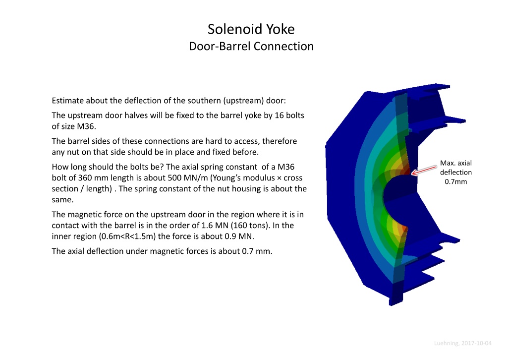
Estimate about the deflection of the southern (upstream) door:
The upstream door halves will be fixed to the barrel yoke by 16 bolts
of size M36.
The barrel sides of these connections are hard to access, therefore
any nut on that side should be in place and fixed before.
How long should the bolts be? The axial spring constant of a M36
bolt of 360 mm length is about 500 MN/m (Young’s modulus × cross
section / length) . The spring constant of the nut housing is about the
same.
The magnetic force on the upstream door in the region where it is in
contact with the barrel is in the order of 1.6 MN (160 tons). In the
inner region (0.6m<R<1.5m) the force is about 0.9 MN.
The axial deflection under magnetic forces is about 0.7 mm.
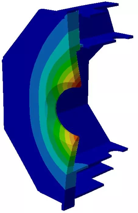
Max. axial
deflection
0.7mm

Door-Barrel Connection
upstream
door
barrel
beam
The design of the door supports presented by
the Dubna group is explained in chapter 4.2.3 of
the solenoid-specs
(
https://edms.cern.ch/document/1713314/6
).
The area around the supports is very crowded
, it
is not easy to get access to parts like
screws and
shims
. Is a solution without access possible?
The support surfaces of the door and the barrel
beam will not be exactly parallel. In order to
keep stresses low the shims have to be precisely
machined so that any deviation from parallelism
is compensated.
An alternative to flat, precisely machined shims
are ball shims, see for instance
http://www.maedler.de/product/1643/2593/2605/kugel
ausgleichsscheiben-mn-6865-rostfrei
Door-Barrel Connection
When the Target Spectrometer (solenoid) will be moved almost the whole weight
of the door halves (2×23 tons upstream) will rest on only 2 bearings at the barrel.
Vertical support of
upstream door (turquoise)
at barrel beam (blue), with
ball shim (yellow)
Same as left-hand,
door hidden
Vertical deflection values
[mm], deflection
magnification factor 1000
Door-Door Connection Upstream
The cam rolls on top of the door halves should be nearer to the vertical
centre-of-gravity (c-o-g) axis of each door half. The maximum force in
beam direction that the cam rolls have to bear is expected to be 10kN.
The vertical c-o-g axis (blue)
of each door half is at about
x=110cm (±)
Cam rolls should
be nearer to the
c-o-g axis (~16cm)
These blocks need to be thicker
(120mm instead of 60mm)
Door-Door Connection Upstream
The cam rolls on top of the door halves should be nearer to the vertical centre-of-gravity (c-o-g) axis.
The maximum force in beam direction that the cam rolls have to bear is expected to be 10kN.
Cam rolls ~16cm
nearer to the c-o-g axis
These blocks need to be thicker
(120mm instead of 60mm). The
minimum force applied on the
connection screws is 40kN.
Downstream Door
Aperture in last plate
Once there was a reason why the aperture in the last plate of the downstream door
had to be much bigger than the apertures in the previous plates. This reason does
not exist anymore. Now, for the last plate, it is sufficient to provide an aperture with
a width of ±520mm and a height of ±260mm.
Downstream Door
Screws and spacers
In order not to waste space for the Muon Counters:
Should the spacers between the door plates be placed nearer to the fixing screws (yellow, see below)?
A more favourable place for squeeze-off screws (magenta) is next to the fixing screws, horizontally.
Holes for fixing the
spacers between plates
(by spot-welding)
Length of the fixing screws:
Mounted through all plates requires a length of 540mm,
maximum standard length for M36 with bolt head is 360mm.
The current set-up of plates, fixing screws, and nut holders is
very elastic. To make it more rigid there should be provided
spacers between the plates next to the screw holes, and the
screws should be shorter.
The assembly force each M36 screw can exert on the door-
barrel connection is about 20 kN (2 tons, wrench torque
250 N·m assumed). A higher force might be problematic for
the nut holders.
20 kN per screw is not enough to
prevent vertical sliding of the
doors (by static friction).
Add-on Beams on Upper Frame Beam
Maximum horizontal
force to be expected
on door rail: 10 kN
Maximum force to
be expected in this
direction: 12 kN
Maximum momentum
(about x-axis) on a
single beam : 10 kN·m
Diagonal beams
debatable, one
instead of 4 seems to
be sufficient
Big Support Beam
In the southern support beam 2 holes with 200mm diameter are needed.
Rips on this side
might be omitted.
In a complex solenoid yoke barrel connection, assessing the deflection of the door is crucial. With specific bolt sizes and spring constants, as well as magnetic forces affecting the door, precise calculations are required to maintain stability. The design intricacies and challenges of supporting the door within the assembly are highlighted, emphasizing the need for meticulous precision. Various components like bolts, nuts, shims, and bearings play essential roles in ensuring structural integrity and minimizing deflection under different forces.

Download Presentation

Please find below an Image/Link to download the presentation.
The content on the website is provided AS IS for your information and personal use only. It may not be sold, licensed, or shared on other websites without obtaining consent from the author.If you encounter any issues during the download, it is possible that the publisher has removed the file from their server.
You are allowed to download the files provided on this website for personal or commercial use, subject to the condition that they are used lawfully. All files are the property of their respective owners.
The content on the website is provided AS IS for your information and personal use only. It may not be sold, licensed, or shared on other websites without obtaining consent from the author.
E N D
Presentation Transcript
Solenoid Yoke Door-Barrel Connection Estimate about the deflection of the southern (upstream) door: The upstream door halves will be fixed to the barrel yoke by 16 bolts of size M36. The barrel sides of these connections are hard to access, therefore any nut on that side should be in place and fixed before. Max. axial deflection 0.7mm How long should the bolts be? The axial spring constant of a M36 bolt of 360 mm length is about 500 MN/m (Young s modulus cross section / length) . The spring constant of the nut housing is about the same. The magnetic force on the upstream door in the region where it is in contact with the barrel is in the order of 1.6 MN (160 tons). In the inner region (0.6m<R<1.5m) the force is about 0.9 MN. The axial deflection under magnetic forces is about 0.7 mm. Luehning, 2017-10-04
Door-Barrel Connection The design of the door supports presented by the Dubna group is explained in chapter 4.2.3 of the solenoid-specs (https://edms.cern.ch/document/1713314/6). upstream door The area around the supports is very crowded, it is not easy to get access to parts like screws and shims. Is a solution without access possible? The support surfaces of the door and the barrel beam will not be exactly parallel. In order to keep stresses low the shims have to be precisely machined so that any deviation from parallelism is compensated. An alternative to flat, precisely machined shims are ball shims, see for instance barrel beam http://www.maedler.de/product/1643/2593/2605/kugel ausgleichsscheiben-mn-6865-rostfrei Luehning, 2017-10-04
Door-Barrel Connection When the Target Spectrometer (solenoid) will be moved almost the whole weight of the door halves (2 23 tons upstream) will rest on only 2 bearings at the barrel. Vertical support of upstream door (turquoise) at barrel beam (blue), with ball shim (yellow) Same as left-hand, door hidden Vertical deflection values [mm], deflection magnification factor 1000 Luehning, 2017-10-04
Door-Door Connection Upstream The cam rolls on top of the door halves should be nearer to the vertical centre-of-gravity (c-o-g) axis of each door half. The maximum force in beam direction that the cam rolls have to bear is expected to be 10kN. The vertical c-o-g axis (blue) of each door half is at about Cam rolls should be nearer to the c-o-g axis (~16cm) These blocks need to be thicker (120mm instead of 60mm) x=110cm ( ) Luehning, 2017-10-04
Door-Door Connection Upstream The cam rolls on top of the door halves should be nearer to the vertical centre-of-gravity (c-o-g) axis. The maximum force in beam direction that the cam rolls have to bear is expected to be 10kN. Cam rolls ~16cm nearer to the c-o-g axis These blocks need to be thicker (120mm instead of 60mm). The minimum force applied on the connection screws is 40kN. Luehning, 2017-10-04
Downstream Door Aperture in last plate Once there was a reason why the aperture in the last plate of the downstream door had to be much bigger than the apertures in the previous plates. This reason does not exist anymore. Now, for the last plate, it is sufficient to provide an aperture with a width of 520mm and a height of 260mm. Luehning, 2017-10-04
Downstream Door Screws and spacers In order not to waste space for the Muon Counters: Should the spacers between the door plates be placed nearer to the fixing screws (yellow, see below)? A more favourable place for squeeze-off screws (magenta) is next to the fixing screws, horizontally. Length of the fixing screws: Mounted through all plates requires a length of 540mm, maximum standard length for M36 with bolt head is 360mm. The current set-up of plates, fixing screws, and nut holders is very elastic. To make it more rigid there should be provided spacers between the plates next to the screw holes, and the screws should be shorter. The assembly force each M36 screw can exert on the door- barrel connection is about 20 kN (2 tons, wrench torque 250 N m assumed). A higher force might be problematic for the nut holders. 20 kN per screw is not enough to prevent vertical sliding of the doors (by static friction). Holes for fixing the spacers between plates (by spot-welding) Luehning, 2017-10-04
Add-on Beams on Upper Frame Beam Diagonal beams debatable, one instead of 4 seems to be sufficient Maximum force to be expected in this direction: 12 kN Maximum momentum (about x-axis) on a single beam : 10 kN m Maximum horizontal force to be expected on door rail: 10 kN Luehning, 2017-10-04
Big Support Beam In the southern support beam 2 holes with 200mm diameter are needed. Rips on this side might be omitted. Luehning, 2017-10-04