Software Design and Development

Software Design and
Development
Computer Architecture

Computing Science
Learning Objectives
By the end of this topic you will be able to:
•
describe the function of the registers, the arithmetic and logic
unit and the control unit in a processor;
•
describe the role of the control, address and data buses in the
fetch execute cycle;
•
describe how cache memory affects processor performance
;
•
describe modern trends in computer architecture;
Learning Objectives
By the end of this topic you will be able to:
•
understand what an emulator is and how it is used;
•
describe the concept of a virtual machine;
•
understand the influence that mobile devices have on the
software development process.
Processor components
Processors have three main components
•
Arithmetic and Logic Unit (ALU)
•
Control; Unit
•
Registers
Processor components
•
The Arithmetic and Logic Unit performs
calculations
•
The Control Unit loads, decodes and executes
instructions
•
The Registers are small memory locations
used by the processor
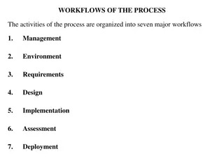
Buses
Buses
are the lines which connect the CPU to the
main memory
There are three buses
–
Data bus
–
Address bus
–
Control bus
Links between Processor and memory
Address Bus
Data Bus
Control Bus
Processor
Memory
Registers
•
Registers are temporary storage areas in the processor
which can be used to hold:
–
The address of the next instruction (Program Counter)
–
The address where data is to be read from or written to
(Address Register)
–
The result of the last calculation (Accumulator)
–
Data or instructions transferred between the CPU and
memory (Data Register)
–
The current instruction being decoded (Instruction Register)
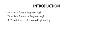
Registers
Arithmetic
and Logic
Unit
Control
Unit
Accumulator
Instruction
register
Program Counter
Address register
Data register
Memory
Control lines
Address Bus
Data Bus
The Address Bus:
The address bus is a 1 way bus
1.
The processor sets up the address register
with the address of the memory location
to be accessed
2.
The processor activates the read or write
line on the control bus
3.
Data is then transferred to or from the
data register via the data bus
The Data Bus
Memory Read / write Operation
•
The data bus is a 2 way bus
•
The memory location to be read from or
written to is set up with the address bus
•
The read or write line is activated on the
control bus
•
The data is transferred to or from the data
register via the data bus
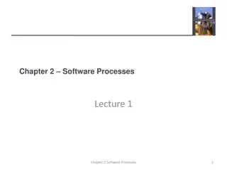
Read Operation
Address Bus
Data Bus
Control Bus
Processor
Memory
11011011010100000
11011011010100000
11011011010100111
11011011010100111
Read line
Data Register
Address Register
Control Unit
11011011010100000
Program Counter
Read Operation
Address Bus
Data Bus
Control Bus
Processor
Memory
11011011010100000
11011011010100000
11011011010100111
11011011010100111
Read line
Data Register
Address Register
Control Unit
11011011010100000
Program Counter
Read Operation
Address Bus
Data Bus
Control Bus
Processor
Memory
11011011010100000
11011011010100000
11011011010100111
11011011010100111
Read line
Data Register
Address Register
Control Unit
11011011010100000
Program Counter
Read Operation
Address Bus
Data Bus
Control Bus
Processor
Memory
11011011010100000
11011011010100000
11011011010100111
11011011010100111
Read line
Data Register
Address Register
Control Unit
11011011010100000
Program Counter
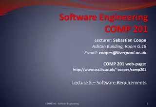
Write Operation
Processor
Memory
11011011010100000
11011011010100111
11011011010100000
11011011010100111
Write line
Address Bus
Control Bus
Data Register
Address Register
Control Unit
Data Bus
11011011010100001
Program Counter
Write Operation
Processor
Memory
11011011010100000
11011011010100111
11011011010100000
11011011010100111
Write line
Address Bus
Control Bus
Data Register
Address Register
Control Unit
Data Bus
11011011010100001
Program Counter
Write Operation
Processor
Memory
11011011010100000
11011011010100111
11011011010100000
11011011010100111
Write line
Address Bus
Control Bus
Data Register
Address Register
Control Unit
Data Bus
11011011010100001
Program Counter
Write Operation
Processor
Memory
11011011010100000
11011011010100111
11011011010100000
11011011010100111
Write line
Address Bus
Control Bus
Data Register
Address Register
Control Unit
Data Bus
11011011010100001
Program Counter
The Fetch - Execute cycle
Fetch Instruction
Decode Instruction
Execute Instruction
The Fetch - Execute cycle in detail
•
Transfer Program Counter (PC) to Memory Address
Register (MAR)
•
Increment the Program Counter
•
Activate Read line (via Control bus)
•
Transfer instruction to Data Register (via Data bus)
and then to Control Unit
•
Decode Instruction
•
Execute Instruction
The contents of the Program Counter are
copied into the Address Register
Address Bus
Data Bus
Control Bus
Processor
Memory
11011011010100000
11011011010100000
11011011010100111
11011011010100111
Read line
Data Register
Address Register
Control Unit
11011011010100000
Program Counter
Instruction Register
Instruction Register
The Program Counter is incremented
Processor
Memory
11011011010100000
11011011010100111
11011011010100000
11011011010100111
Write line
Address Bus
Control Bus
Data Register
Address Register
Control Unit
Data Bus
11011011010100001
Program Counter
Instruction Register
The read line is activated and
the contents of
memory at the location are copied into the
Data Register
Address Bus
Data Bus
Control Bus
Processor
Memory
11011011010100000
11011011010100000
11011011010100111
11011011010100111
Read line
Data Register
Address Register
Control Unit
11011011010100000
Program Counter
Instruction Register
1101101101010011
The Contents of the Data Register are
copied into the Instruction Register
Processor
Memory
11011011010100000
11011011010100111
11011011010100000
11011011010100111
Write line
Address Bus
Control Bus
Data Register
Address Register
Control Unit
Data Bus
11011011010100001
Program Counter
The Instruction is decoded
Processor
Memory
11011011010100000
11011011010100111
11011011010100000
11011011010100111
Write line
Address Bus
Control Bus
Data Register
Address Register
Control Unit
Data Bus
11011011010100001
Program Counter
Instruction Register
1101101101010011
The Instruction is executed
Processor
Memory
11011011010100000
11011011010100111
11011011010100000
11011011010100111
Write line
Address Bus
Control Bus
Data Register
Address Register
Control Unit
Data Bus
11011011010100001
Program Counter
Instruction Register
1101101101010011
Cache memory
Cache memory is memory that can be accessed
more quickly than regular RAM.
Copies of instructions and data that are
frequently used are stored here
Processor will try to predict which instructions
are needed and load them into cache
Cache memory
Accessing cache memory is quicker because
•
It uses faster (and more expensive) memory chips
•
It is closer to the processor than normal RAM
Cache memory
Cache memory comes in different levels
•
Level 1 (L1) cache, which is extremely fast but
relatively small, is located close to the processor.
•
Level 2 (L2) cache is located half-way between
the process and the system bus; it is fairly fast
and medium-sized.
•
Level 3 (L3) cache is relatively large and close to
RAM.
Modern trends in architecture
Strategies used to improve processor
performance
•
Speeding up the processor
•
Increasing the instruction size executed in
one operation
•
Reducing the size of the transistors
Modern trends in architecture
•
Increasing on-chip memory
•
Parallel computing
Possible developments in future
•
Quantum computing
•
Optical computing
Emulators
An Emulator is a piece of software that allows a
computer system to emulate another computer
system.
They can be used for several purposes. For example
To allow programs written for obsolete machine to
run on a modern system. This is often to allow
computer games written for consoles or arcade
systems to run on modern machines
Emulators
A second reason is to allow the development of
software for systems that have not yet been built.
This allows software for a new system to be
available when the system is first launched.
Virtual machines are also examples of emulators
Virtual machines
Virtual machines are again pieces of software that allow
multiple types of software to run on a single machine.
They can be used to allow several OS to run on a single
machine, or several copies of the same OS to run on one
machine.
They can also be used to provide program portability. A
single version of a program can be created and then a
virtual machine created for each OS that it has to run
with. This is the process that programs written in Java use
with the Java Virtual Machine.
Mobile devices
Rise in use of mobile devices has led to
•
Need for emulators for development of software
•
Redesign of displays for smaller screen sizes
•
Need for touch screen technology
•
Dealing with more limited bandwith
•
Integrating facilities like GPS
This content covers the essential components of processor design, including registers, arithmetic and logic units, control units, and buses. It explains the role of cache memory, modern trends in computer architecture, and the influence of mobile devices on software development. Learn about processor components and their functions, the importance of buses in connecting the CPU to memory, and the significance of registers in temporary storage. Discover the impact of emulator and virtual machine technology in software development processes.

Download Presentation

Please find below an Image/Link to download the presentation.
The content on the website is provided AS IS for your information and personal use only. It may not be sold, licensed, or shared on other websites without obtaining consent from the author.If you encounter any issues during the download, it is possible that the publisher has removed the file from their server.
You are allowed to download the files provided on this website for personal or commercial use, subject to the condition that they are used lawfully. All files are the property of their respective owners.
The content on the website is provided AS IS for your information and personal use only. It may not be sold, licensed, or shared on other websites without obtaining consent from the author.
E N D
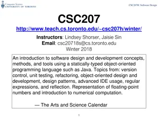
Presentation Transcript
Computing Science Software Design and Development Computer Architecture
Learning Objectives By the end of this topic you will be able to: describe the function of the registers, the arithmetic and logic unit and the control unit in a processor; describe the role of the control, address and data buses in the fetch execute cycle; describe how cache memory affects processor performance; describe modern trends in computer architecture;
Learning Objectives By the end of this topic you will be able to: understand what an emulator is and how it is used; describe the concept of a virtual machine; understand the influence that mobile devices have on the software development process.
Processor components Processors have three main components Arithmetic and Logic Unit (ALU) Control; Unit Registers
Processor components The Arithmetic and Logic Unit performs calculations The Control Unit loads, decodes and executes instructions The Registers are small memory locations used by the processor
Buses Buses are the lines which connect the CPU to the main memory There are three buses Data bus Address bus Control bus
Links between Processor and memory Processor Address Bus Control Bus Data Bus Memory
Registers Registers are temporary storage areas in the processor which can be used to hold: The address of the next instruction (Program Counter) The address where data is to be read from or written to (Address Register) The result of the last calculation (Accumulator) Data or instructions transferred between the CPU and memory (Data Register) The current instruction being decoded (Instruction Register)
Registers Arithmetic and Logic Unit Control Unit Program Counter Instruction register Accumulator Address register Data register Address Bus Data Bus Control lines Memory
The Address Bus: The address bus is a 1 way bus 1. The processor sets up the address register with the address of the memory location to be accessed 2. The processor activates the read or write line on the control bus 3. Data is then transferred to or from the data register via the data bus
The Data Bus Memory Read / write Operation The data bus is a 2 way bus The memory location to be read from or written to is set up with the address bus The read or write line is activated on the control bus The data is transferred to or from the data register via the data bus
Read Operation Program Counter Processor 11011011010100000 Control Unit Address Register Data Register Read line 11011011010100000 11011011010100111 Address Bus Control Bus 11011011010100000 11011011010100111 Data Bus Memory
Read Operation Program Counter Processor 11011011010100000 Control Unit Address Register Data Register Read line 11011011010100000 11011011010100111 Address Bus Control Bus 11011011010100000 11011011010100111 Data Bus Memory
Read Operation Program Counter Processor 11011011010100000 Control Unit Address Register Data Register Read line 11011011010100000 11011011010100111 Address Bus Control Bus 11011011010100000 11011011010100111 Data Bus Memory
Read Operation Program Counter Processor 11011011010100000 Control Unit Address Register Data Register Read line 11011011010100000 11011011010100111 Address Bus Control Bus 11011011010100000 11011011010100111 Data Bus Memory
Write Operation Program Counter Processor 11011011010100001 Control Unit Address Register Data Register Write line 11011011010100000 11011011010100111 Address Bus Control Bus 11011011010100000 11011011010100111 Data Bus Memory
Write Operation Program Counter Processor 11011011010100001 Control Unit Address Register Data Register Write line 11011011010100000 11011011010100111 Address Bus Control Bus 11011011010100000 11011011010100111 Data Bus Memory
Write Operation Program Counter Processor 11011011010100001 Control Unit Address Register Data Register Write line 11011011010100000 11011011010100111 Address Bus Control Bus 11011011010100000 11011011010100111 Data Bus Memory
Write Operation Program Counter Processor 11011011010100001 Control Unit Address Register Data Register Write line 11011011010100000 11011011010100111 Address Bus Control Bus 11011011010100000 11011011010100111 Data Bus Memory
The Fetch - Execute cycle Fetch Instruction Decode Instruction Execute Instruction
The Fetch - Execute cycle in detail Transfer Program Counter (PC) to Memory Address Register (MAR) Increment the Program Counter Activate Read line (via Control bus) Transfer instruction to Data Register (via Data bus) and then to Control Unit Decode Instruction Execute Instruction
The contents of the Program Counter are copied into the Address Register Program Counter Processor Control Unit 11011011010100000 Instruction Register Address Register Data Register Read line 11011011010100000 11011011010100111 Address Bus Control Bus 11011011010100000 11011011010100111 Data Bus Memory
The Program Counter is incremented Program Counter Processor Control Unit 11011011010100001 Instruction Register Address Register Data Register Write line 11011011010100000 11011011010100111 Address Bus Control Bus 11011011010100000 11011011010100111 Data Bus Memory
The read line is activated and the contents of memory at the location are copied into the Data Register Program Counter Processor Control Unit 11011011010100000 Instruction Register Address Register Data Register Read line 11011011010100000 11011011010100111 Address Bus Control Bus 11011011010100000 11011011010100111 Data Bus Memory
The Contents of the Data Register are copied into the Instruction Register Program Counter Processor Control Unit 11011011010100001 Instruction Register Address Register Data Register 1101101101010011 Write line 11011011010100000 11011011010100111 Address Bus Control Bus 11011011010100000 11011011010100111 Data Bus Memory
The Instruction is decoded Program Counter Processor Control Unit 11011011010100001 Instruction Register Address Register Data Register 1101101101010011 Write line 11011011010100000 11011011010100111 Address Bus Control Bus 11011011010100000 11011011010100111 Data Bus Memory
The Instruction is executed Program Counter Processor Control Unit 11011011010100001 Instruction Register Address Register Data Register 1101101101010011 Write line 11011011010100000 11011011010100111 Address Bus Control Bus 11011011010100000 11011011010100111 Data Bus Memory
Cache memory Cache memory is memory that can be accessed more quickly than regular RAM. Copies of instructions and data that are frequently used are stored here Processor will try to predict which instructions are needed and load them into cache
Cache memory Accessing cache memory is quicker because It uses faster (and more expensive) memory chips It is closer to the processor than normal RAM
Cache memory Cache memory comes in different levels Level 1 (L1) cache, which is extremely fast but relatively small, is located close to the processor. Level 2 (L2) cache is located half-way between the process and the system bus; it is fairly fast and medium-sized. Level 3 (L3) cache is relatively large and close to RAM.
Modern trends in architecture Strategies used to improve processor performance Speeding up the processor Increasing the instruction size executed in one operation Reducing the size of the transistors
Modern trends in architecture Increasing on-chip memory Parallel computing Possible developments in future Quantum computing Optical computing
Emulators An Emulator is a piece of software that allows a computer system to emulate another computer system. They can be used for several purposes. For example To allow programs written for obsolete machine to run on a modern system. This is often to allow computer games written for consoles or arcade systems to run on modern machines
Emulators A second reason is to allow the development of software for systems that have not yet been built. This allows software for a new system to be available when the system is first launched. Virtual machines are also examples of emulators
Virtual machines Virtual machines are again pieces of software that allow multiple types of software to run on a single machine. They can be used to allow several OS to run on a single machine, or several copies of the same OS to run on one machine. They can also be used to provide program portability. A single version of a program can be created and then a virtual machine created for each OS that it has to run with. This is the process that programs written in Java use with the Java Virtual Machine.
Mobile devices Rise in use of mobile devices has led to Need for emulators for development of software Redesign of displays for smaller screen sizes Need for touch screen technology Dealing with more limited bandwith Integrating facilities like GPS